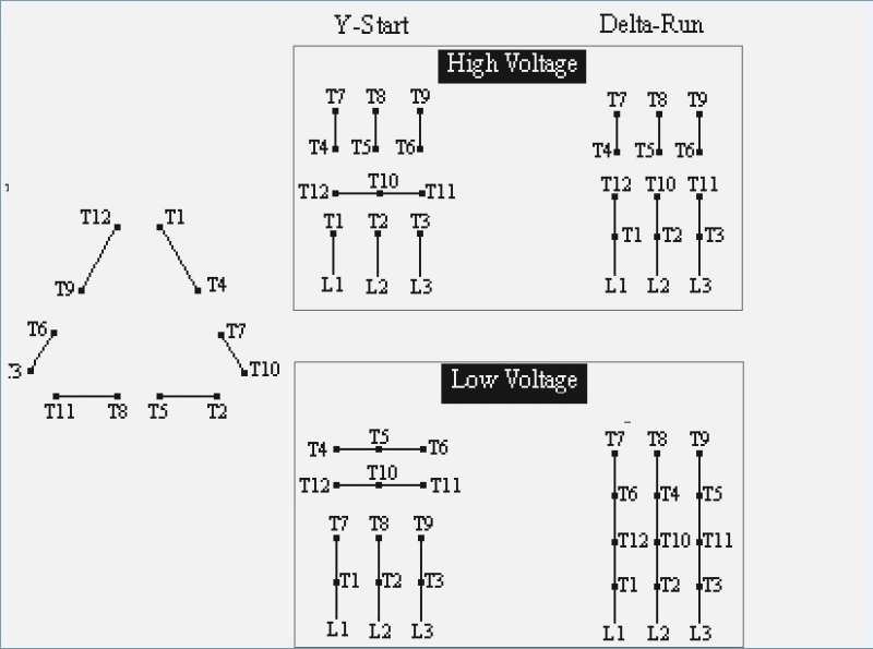
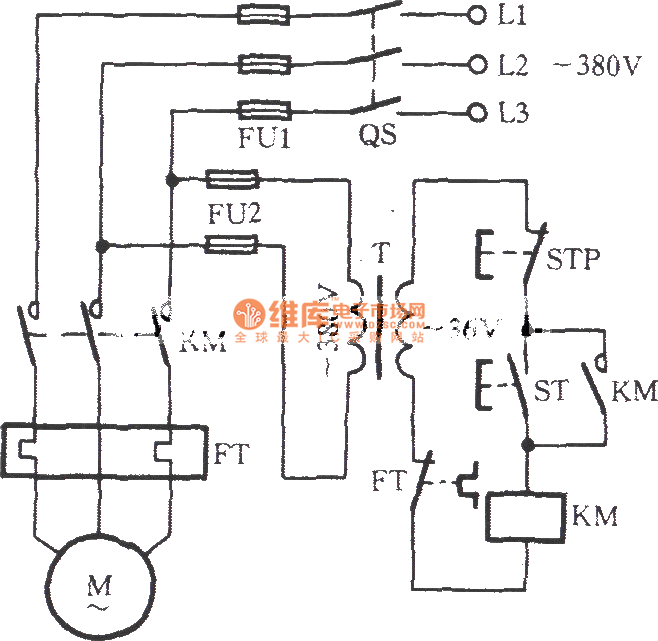
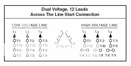
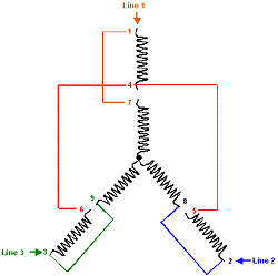
A three phase motor must be wired based on the diagram on the faceplate. 3 phase motor wiring diagram 12 leads sample how to check polarity of each winding in 3 phase motor.

Techtop Electric Motors
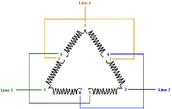
3 phase low voltage wiring diagram. That being said there is a wide range of different motors and what you have on hand can be completely different. Single phase electric motor wiring tutorial. Connect motor leads 9 and 3 with the blue l3 conductor. The phase angle difference between voltage and current of each phase is not necessarily 0 and is dependent on the type of load impedance z y. Split phase motor dual voltage reversible rotation capacitor motor single phase wiring diagrams always use wiring diagram supplied on motor nameplate. Community answer on a 12 wire motor wired for high voltage ie 480v 10t 11t and 12t must be connected together but not connected to anything else.
On a high voltage motor with 10t 11t 12t as a dot and not going to anything on the wiring diagram do i leave them all separate and not connected to anything. Pete vree 16304 views. 3 phase 6 lead motor wiring diagram elegant awesome 12 lead 3 phase. Baldor weg leeson duration. A three phase motor is more efficient than a single phase motor because of the peculiarities of alternating current ac. Busbars carries this three phase power and from which individual connections are brought out to individual loads through cables.
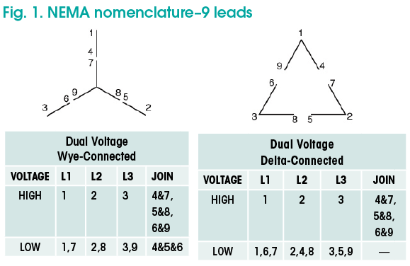
Connect motor leads 8 and 2 with the red l2 conductor. When a motors power supply is brought in from three wires instead of just one with the power delivery cycling through each of these in sequence hence the a part of ac it permits an effective power level that is 3 times higher about 1728 times higher than a. 3 phase low voltage motor wiring diagram i asked what the voltage was a high limit control a low water cutoff as a safety device and a thermostat setting the comfort level. Dual voltage 3 phase 9 lead wye motor connections 2 duration. Connect motor leads 7 and 1 with the black l1 conductor. Connect motor leads 4 5 and 6 together.
Make the connections for low voltage 230 volt wiring. Typical connection diagrams three phase motors y start delta. The figure below shows schematic diagram for industrial three phase wiring. In the united states for low voltage motors below 600v you can expect either 230v or 460v. However the relative phase angle between each pair of lines 1 to 2 2 to 3 and 3 to 1 will still be 120. Three phase power from the utilities is connected to the main breaker through three phase energy meter.
The first step is to figure out the voltage of your phases. Inductive and capacitive loads will cause current to either lag or lead the voltage. Typical connection diagrams three phase motors y start delta.

