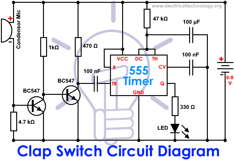
The main component of the circuit is the electric condenser mic which has been used as a sound sensor. Working and schematic diagram of clap swith circuit.
Very Sensitive Clap Switch Circuit
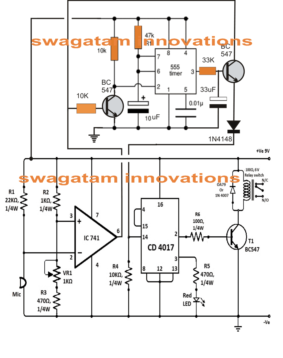
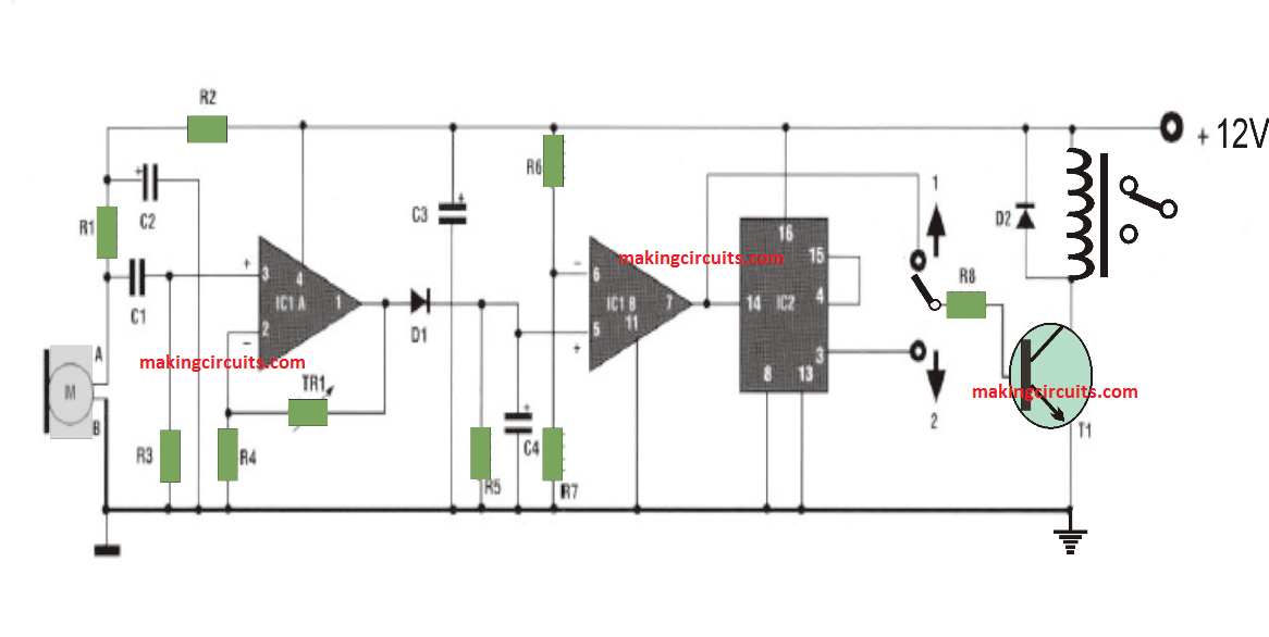
Circuit diagram of clap switch using 555. Resistors 100 ω r1 560 ω r2 46 kω r3 18 kω 3 r4 33 kω r5. It works as a switch which makes devices on and off by making a clap sound. Although its name is clap switch but it can be turned on by any sound of approximately same pitch of clap soundthe main component of this clap switch circuit is the electric condenser mic which has been used as a sound sensorcondenser mic basically converts sound energy into electrical energy. In this tutorial we will learn how to make a clap switch circuit using a 555 timer ica clap switch circuit can turn onoff any electrical component by the sound of a clap. Cd 4017 ic ic2. A resistor is an electronic component which opposes the flow of current or prevents.
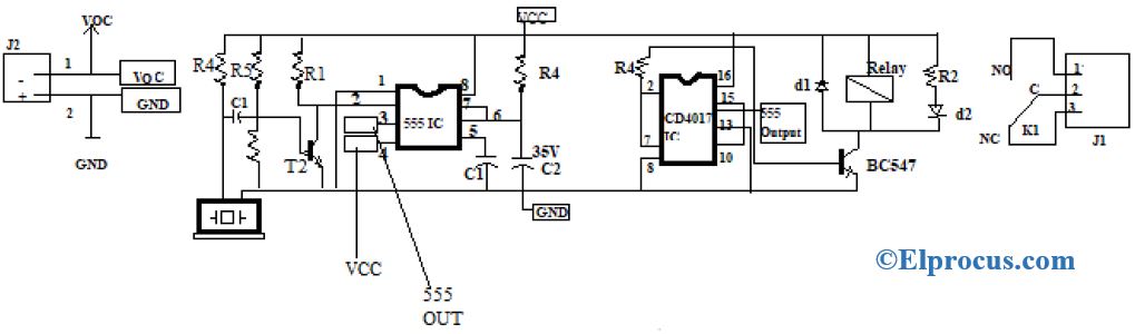
Although the name of the circuit is clap switch it can be turned on by any sound which has pitch similar to a clap sound. This is another clap on off circuit diagram using 555 timer and 7474 icwhen clap the load is switch on and when again clapped then load is switch off. A relay is a switching device which is used to switch the circuit on when required and turn off whenever required. In this circuit 555 timer ic and 7474 dual positive. This is a simple electronic project and mostly used to turn on and off ac appliances with the help of sound. Clap switch circuit using 555 and 4017.
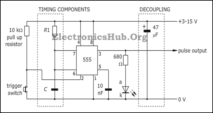
Share on tumblr this clap switch circuit using ic 555 is a hobby circuit makes led to glow while you clap or make louder noise. The clap switch circuit is yet another simple and cool project. Clap switch is an interesting hobby circuit which turns on the lights with a clap sound. When you clap once the relay is activated and the light or any load is turned on. When you clap for the second time the relay is deactivated and the light is turned off. 555 ic ic 1.
Condenser mic basically converts sound energy into. In the first circuit i will control a single relay using clap switch. Circuit is work by the detection of clap sound. This clap operated on off switch circuit is useful to on off any appliance. This is simple clap switch circuit diagram. It consists of condenser mic to pick sound of the clap and convert from sound energy to electrical energy which is then used to trigger 555 timer output where led is connected.
This construction will give mono pulse when trigger received from mic the duration of pulse time varies respect to r2 and c2 connected with ic555. Clap switch circuit is a basic electronics project made from the basic components such as ic 555 timer bc 547 transistors led resistors capacitors etc. You can use this circuit concept in many ways to activate sound based project. Although its name is clap switch but it can be turned on by any sound of about same pitch of clap sound. Share on tumblr remote access to electrical devices are makes us comfortable and if you can control electric device with clap then it makes you very joyful and here we have prototype a simple clap on clap off switch using 555 timer and this circuit can help us to control any electric device here for an example we have taken electric bulb. The main components of the circuit are.
Gallery of Circuit Diagram Of Clap Switch Using 555