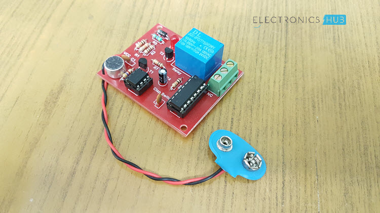
Although its name is clap switch but it can be turned on by any sound of about same pitch of clap sound. Clap switch has the ability to turn onoff any electrical component or circuit by the clap sound.

4 Simple Clap Switch Circuits Tested Homemade Circuit
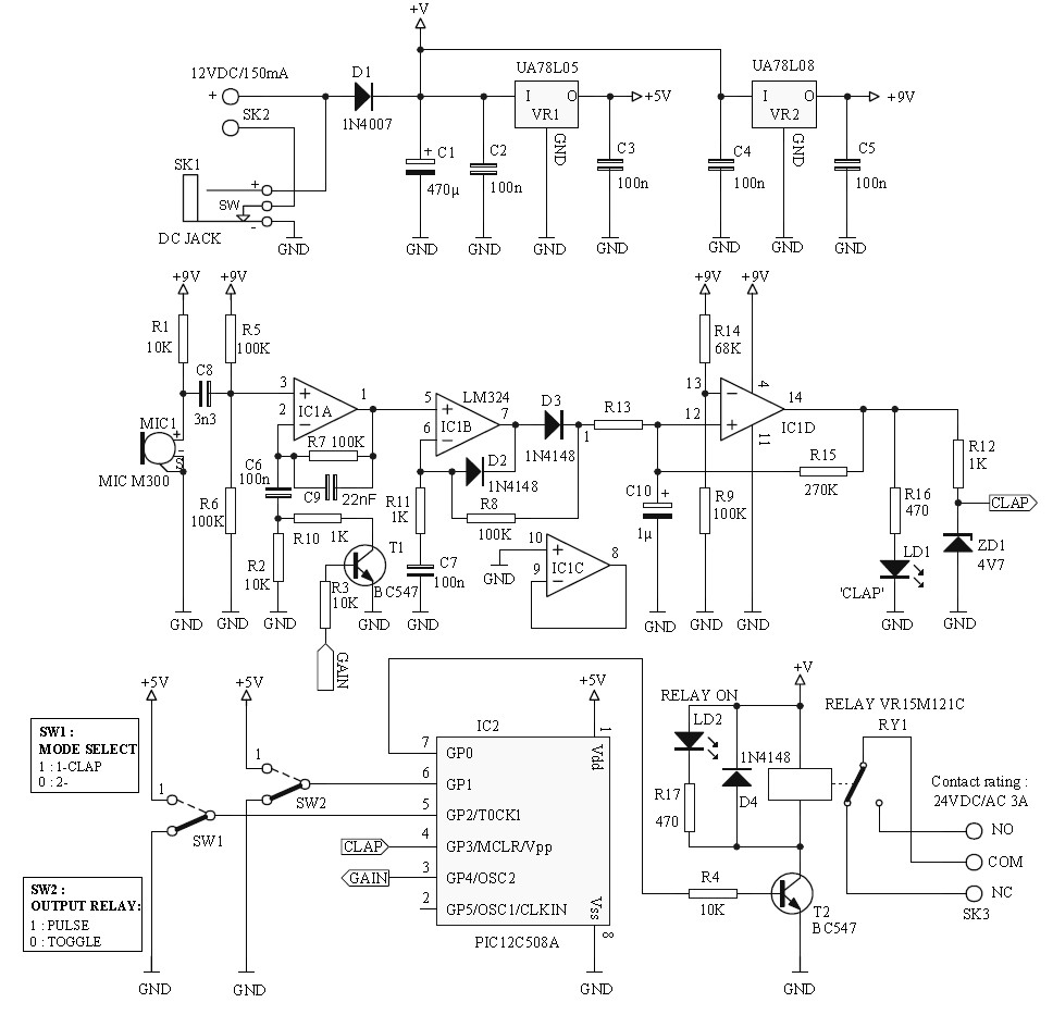
Clap sensor light switch circuit diagram. When you clap for the second time the relay is deactivated and the light is turned off. Condenser mic basically converts sound energy into. Multi electric 161466 views. In the first circuit i will control a single relay using clap switch. Clap switch is a basic electronics mini project made with the help of the basic components. Introduction to clap switch circuit.
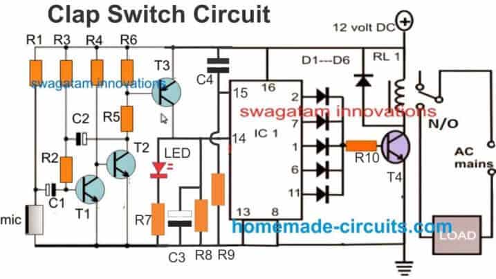
How to make sound clap switch lights on off control light fan with clap using cd4017 ic duration. Clap switch is an interesting hobby circuit which turns on the lights with a clap sound. When you clap once the relay is activated and the light or any load is turned on. When we power up the circuit the current will flow from source to the ve mic and leaves at ve. The main component of the circuit is the electric condenser mic which has been used as a sound sensor. The claps must be in quick succession as seen in the video below or else it does not work which is the entire point of the circuit i will go into detail about the circuitry.
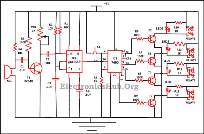
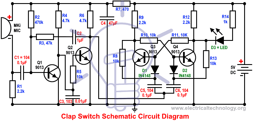
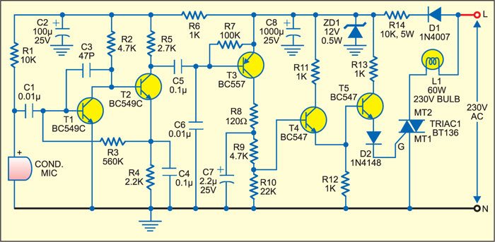
With ic 555 timers and without 555 timer. By default t1 is on and t2 is off. Although its name is clap switch but it can be turned on by any sound of approximately same pitch of clap soundthe main component of this clap switch circuit is the electric condenser mic which has been used as a sound sensorcondenser mic basically converts sound energy into electrical energy. Basically it is a sound activated switch circuit that has a condenser mic that picks up the sound converted in electronic signal and then is passed to the transistor that switches on the led lightin this case the 220v light for a period of max 1 minutthis is a clap on circuit already designed so we have to just assemble ita more advanced clap on switch will follow in the next episodes. It works as a switch which makes devices on and off by making a clap sound. We will use two basic clap switch circuit diagrams ie.
It is relatively easy to make a hardware only clap onoff circuit but i wanted to create a circuit that required two claps to switch on and two claps to switch off. According to that all we have to do is to provide a low signal to the 555s trigger pin pin 2 to switch on the light for a desired time. Clap switch circuit using 555 and 4017.


