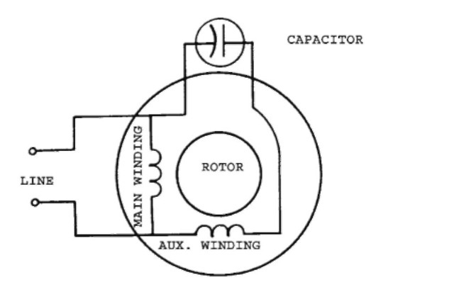
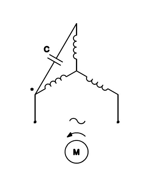
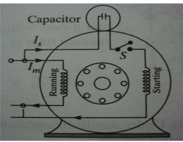
This type of motor is designed to provide strong starting torque and strong running for applications such as large water pumps. Click here to view a capacitor start motor circuit diagram for starting a single phase motor.
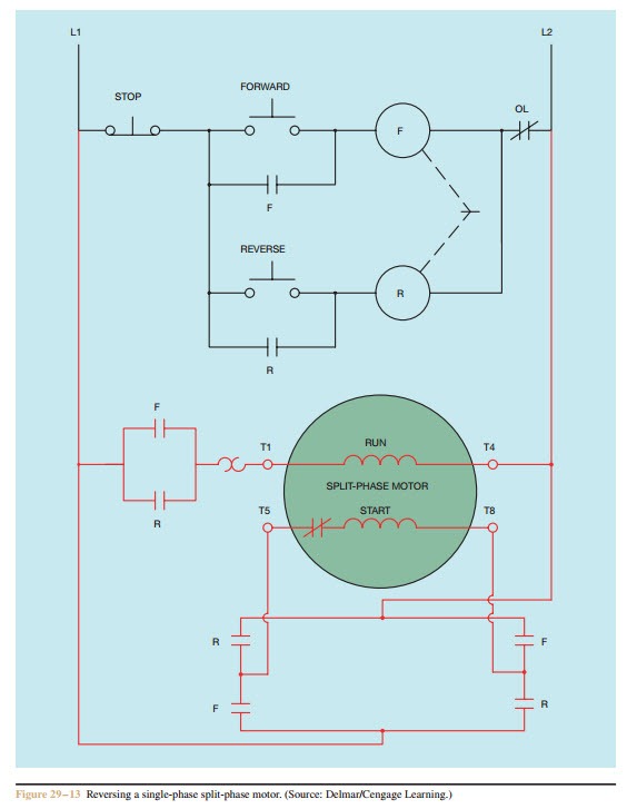
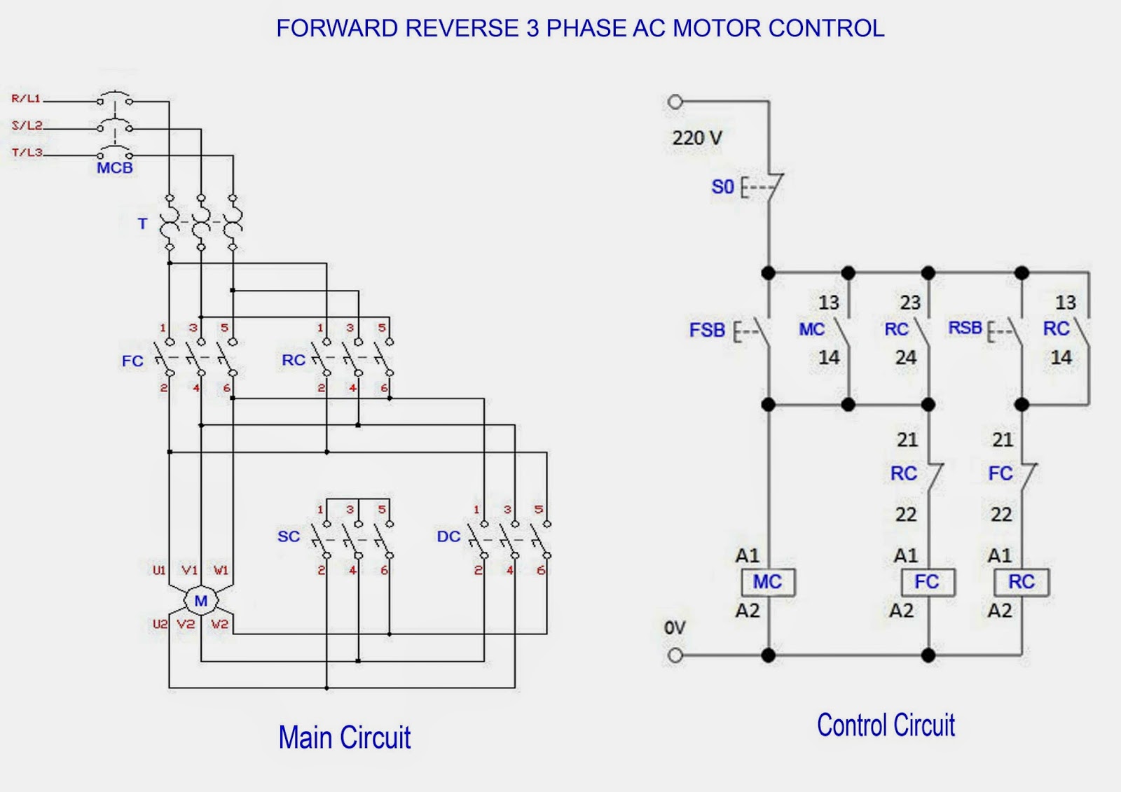
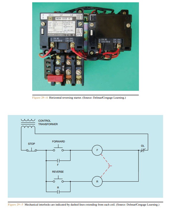
Forward Re Verse Control Developing A Wiring Diagram And
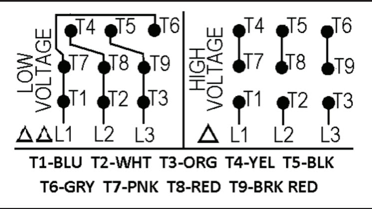
Draw the wiring diagram of single phase 1hp. Diagram dd6 diagram dd7 m 1 ln e diagram dd8 ln e l1 l2 l3 sc z1 u2 z2 u1 cap. Single phase motors are used to power everything from fans to shop tools to air conditioners. There are a number of single phase motors on various pieces of equipment and what i will try to do here is to explain it as easily as possible. Capacitor start capacitor run induction motors are single phase induction motors that have a capacitor in the start winding and in the run winding as shown in figure 12 and 13 wiring diagram. For all other single phase wiring diagrams refer to the manufacturers data on the motor. Wondering how a capacitor can be used to start a single phase motor.
Today i am hear to write about submersible pump control box wiring diagram in this post you will complete understood about 3 wire submersible pump wiring diagram which is an single phase submersible pump motor. Some motors allow both 120 volt and 240 volt wiring by providing a combination of wires for doing so. In this video jamie shows you how to read a wiring diagram and the basics of hooking up an electric air compressor motor. Learn how a capacitor start induction run motor is capable of producing twice as much torque of a split phase motor. Why we called a single phase submersible motor a 3 wire submersible that we also know that we have two wire in single phase power supply. Wiring diagram 120 volt motor electric diagrams three phase basic.
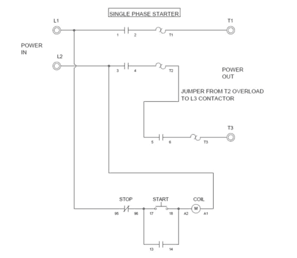
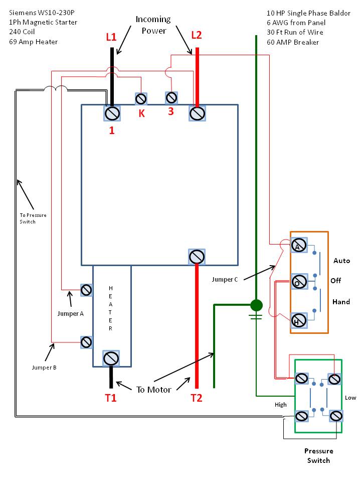
We have had a look at motor testing on the three phase motors and i think we should also have a quick look at the single phase connection diagram. Lets start with the basic diagram of the motor. In the above one phase motor wiring i first connect a 2 pole circuit breaker and after that i connect the supply to motor starter and then i do cont actor coil wiring with normally close push button switch and normally open push button switch and in last i do connection between capacitor. Residential power is usually in the form of 110 to 120 volts or 220 to 240 volts. Baldor motor wiring diagram impremedia net entrancing diagrams. Weg motor starter wiring diagram motors best 3 phase two speed.
Thermal contacts tb white m 1 z2 yellow z1 blue u2 black u1 red bridge l1 and l2 if speed controller sc is not required m 1 ln e white brown blue l1 l2 n sc. These tips can be used on most electric motor brands such as weg baldor. Single phase marathon motor wiring diagram gallery wiring diagram 120 volt motor electric diagrams three phase basic. The above diagram is a complete method of single phase motor wiring with circuit breaker and contactor. Also read about the speed torque characteristics of these motors along with its different types. Wiring a motor for 230 volts is the same as wiring for 220 or 240 volts.

