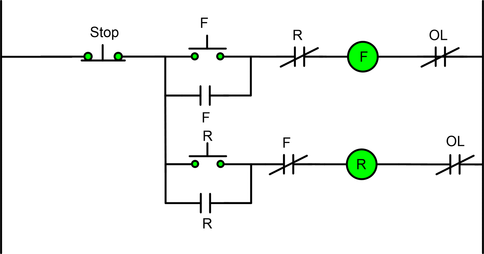
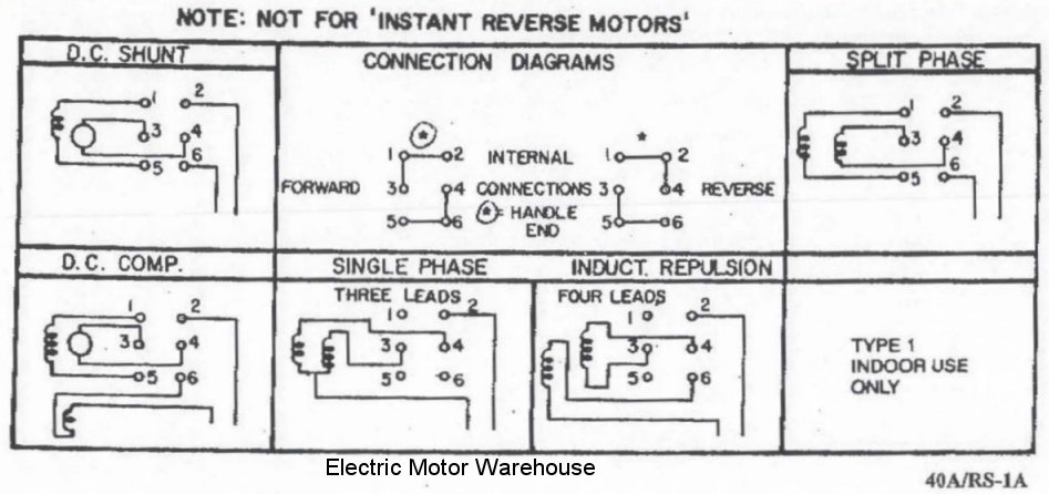
Forward and reverse operation of the motor can be. A motor controller might include a manual or automatic means for starting and stopping the motor selecting forward or reverse rotation selecting and regulating the speed regulating or limiting.
Motor Control Circuit Diagram Forward Reverse C3 Wiring Diagram
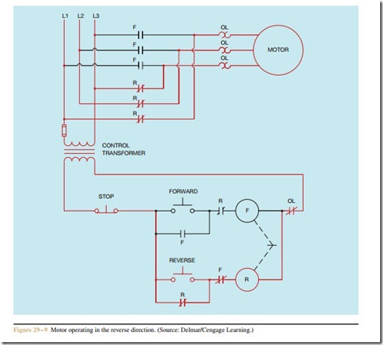
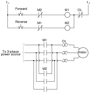
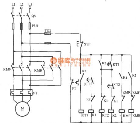
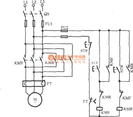
Forward and reverse connection diagram of 3 phase motor. After that the three phase supply goes to thermal overload relay and from thermal overload relay the soppy goes to the 3 phase motor connection plate and provided to 3 phase motor. 800 x 600 px source. Three phase motor connection reverse and forward power and control wiring diagrams. This post is about the 3 phase forward reverse motor control circuit diagram. Three phase motor connection stardelta y δ reverse and forward with timer power control diagram as we have already shared the starting method of three phase motor by star delta starter with timer circuit power and control circuits. Now in the below diagrams three phase motor will rotate in two directions viz forward and reverse.
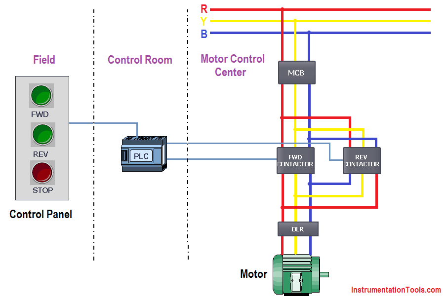
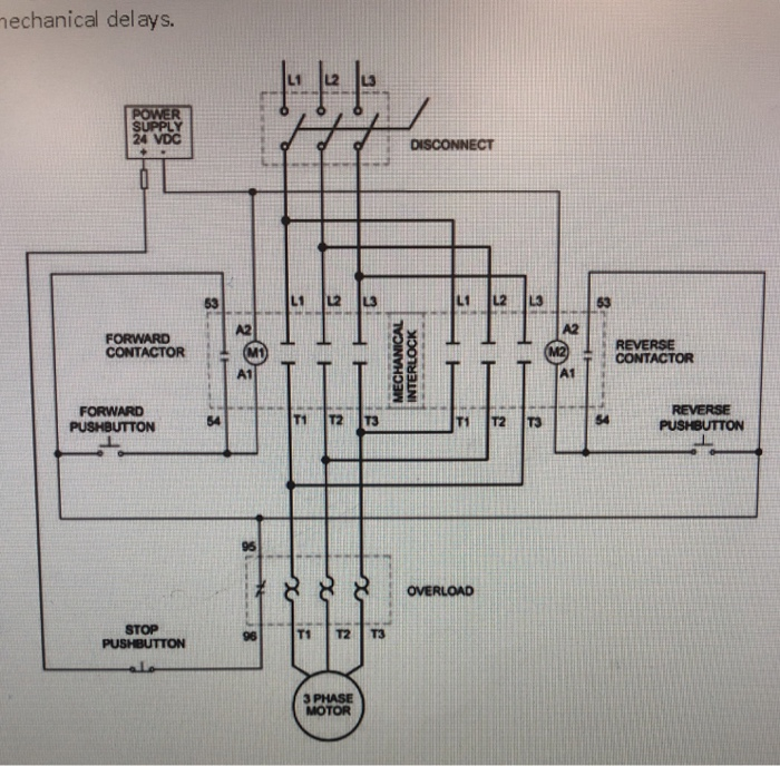
In this post i will share with you the 3 phase motor forward reverse motor control circuit diagrams. Or how make a forward reverse 3 phase motor starter. Nc and no switches to stop motor to run motor forward or reverse. Here connect the 3 phase supply to the over load relay same as input to run the motor in forward direction but in case of the reverse contactor we have to reverse one phase for the reversing of direction of motor as shown in the diagram. As you know that if we change one phase with other phase the 3 phase motor change the rotation direction. It reveals the components of the circuit as simplified forms as well as the power as well as signal links in between the tools.
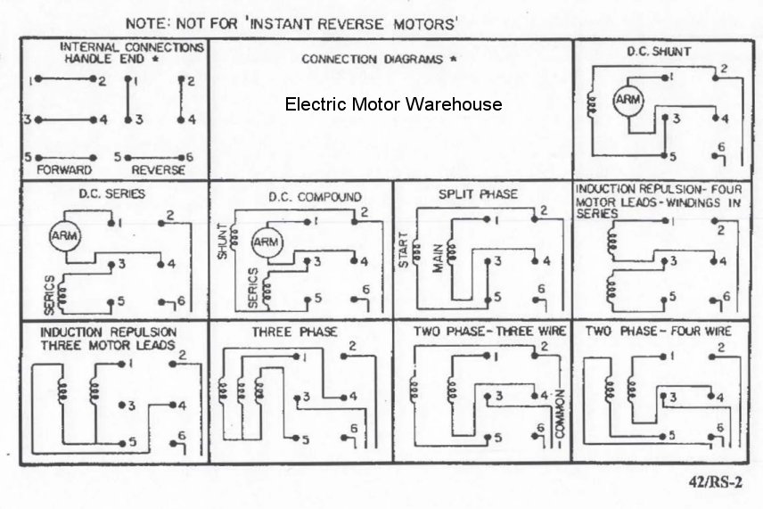
Variety of single phase motor wiring diagram forward reverse. Single phase forward reverse motor wiring diagram concerbiz size. Here i have shown the forward reverse motor control diagram for 3 phase motor. Reverse forward motor control circuit diagram is the today topic. For that we use two magnetic contactors. The forward reverse motor control is used in a system where forward and backward or upward and downward movement in the operation is needed.
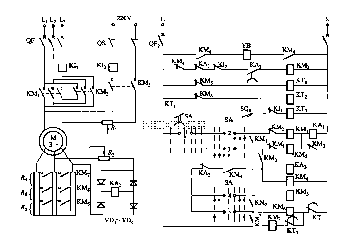
A wiring diagram is a simplified conventional pictorial representation of an electrical circuit. In this post i will gave you two three phase motor controlling diagram for forward reverse connection. I have a conveyor from ground to first floor where would i add the forward and reverse and e stop buttons for the first floor on this diagram. Here are a few of the leading drawings we obtain from various sources we wish these pictures will serve to you and with any luck very appropriate to just what you want about the reversing motor starter wiring diagram is.
