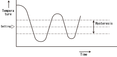
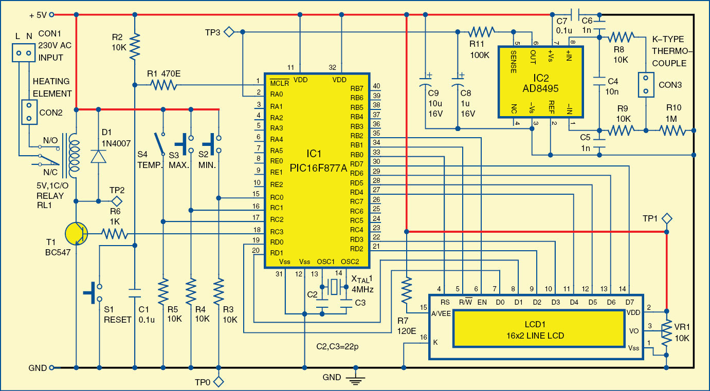
The second opamp a2 functions as a comparator with a hysteresis of about 15. In this post we are going to construct a small greenhouse temperature and humidity controller circuit using arduino which can self regulate its temperature and humidity.

How To Build A Simple Egg Incubator Thermostat Circuit
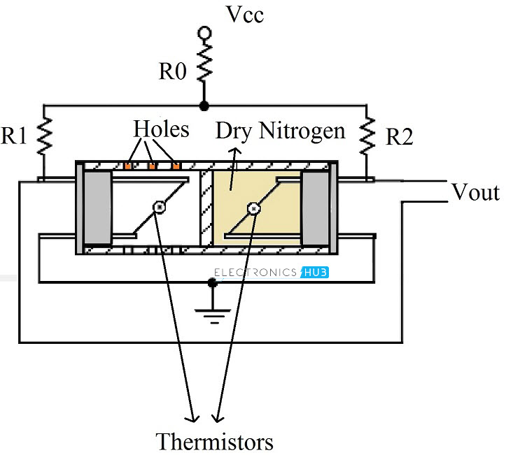
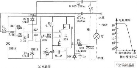
Humidity control circuit diagram. Download it and make it your own. How does the humidity controlled switch works. 1lcd fro displaying the readings of the temperature and humidity 2a relay to control the exhaust and a fan if the humidity is more and the temperature is more respectively. A free customizable digital humidity circuit template is provided to download and print. By the way the above circuit will also give you a precise humidity control if the range is set correctly. Various plants have got diverse specifications for.
You can use it as a start template to draw circuit control or electrical schematic diagrams. Schematic of the humidity sensor circuit. Voltage monitoring circuit for 12 volt lipo battery pack schematic circuit diagram may 25 2020. At a certain humidity level the circuit switches on the load. Mindmaster flow chart mind map org charts. Linear technology application notes.
The first opamp a1 functions as a high impedance. The moisture level is converted to a voltage through r3 in the first part of the circuit. 950mhz 2000mhz analog satellite finder schematic circuit diagram may 28 2020. The relay is opened when the 10k resistor is connected to point a not to point b as shown in the schematic. The simple programmable humidity sensor circuit explained in this article can be used for controlling or maintaining a suitable level of humidity inside a close premise. What is greenhouse plant life require light warm conditions air flow water and nourishment to outlive and cultivate.
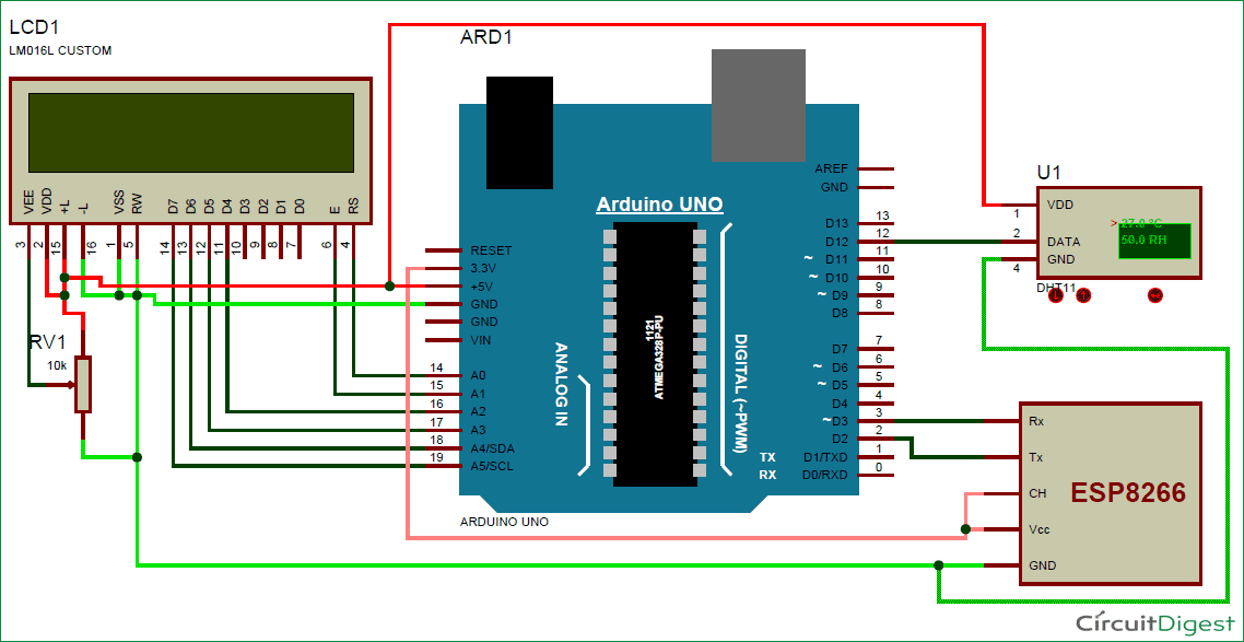
Need circuit diagram of arduino connecting with lcd asap thanks. Circuit diagram of dht11 and lcd with arduino. For this following the circuit diagram given below connect the sensor lcd with the arduino. You can use other sensors like ldr or ntc instead of the copper ones so you can use this circuit for detecting light or temperature. This circuit control diagram template offers plenty of circuit diagram symbols. Quickly get a head start when creating your own digital humidity diagrams.
Now we will display the temperature and humidity readings on the lcd 162 display. To read lower rh down to 10 converting 350uv signals would require a 16 bit converter. Simple led circuits led projects schematic circuit diagram may 26 2020. Synchronizing transistors schematic circuit diagram may 27 2020. A 16 bit adc is expensive so it is much more economical to use a 2 channel 12 bit converter that changes ranges somewhere in the humidity range. Circuits schematic diagram source.
With edraw more complicated basic electrical diagrams could be made easily. Circuit basics on february 27.


