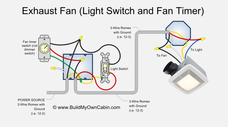
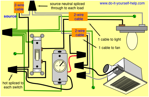
The low voltage relay is located near the in line exhaust fan where it will act as a switch for the 120 volt power for the in line exhaust fan. Wire the fan as shown in figure e using the diagram appropriate to the fan model.
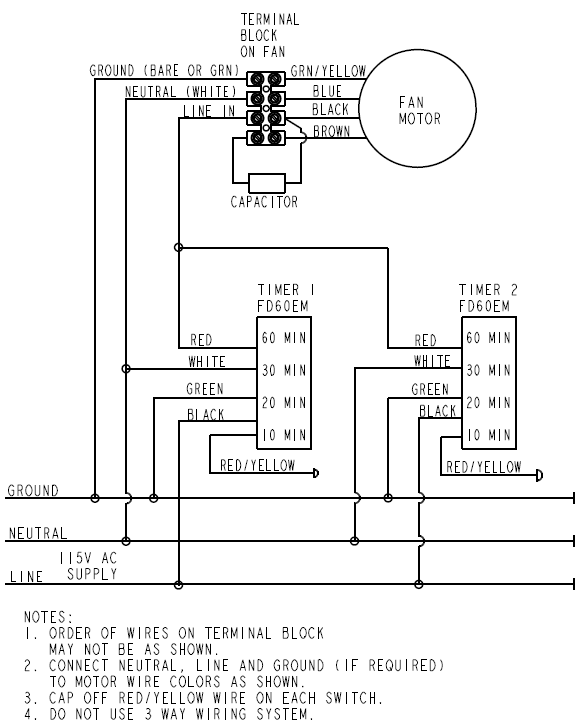
Hvacquick How To S Wiring 1 Fan Serving 2 Baths With 1
In line timer extractor fan wiring diagram. Manrose fan wiring diagram wiring diagram is a simplified adequate pictorial representation of an electrical circuitit shows the components of the circuit as simplified shapes and the gift and signal links between the devices. This wiring plan will simply run the fan when the room light is on. Simple presentation how to wire bathroom extractor fans with timers or humidistat module. A wiring diagram usually gives suggestion just about the relative approach and promise of devices and terminals upon the devices to incite in building or servicing. Monsoon extractor fan wiring diagram. Instead we are going to install a new switch that will turn teh fan on and off.
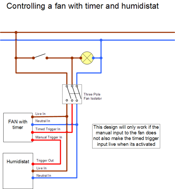
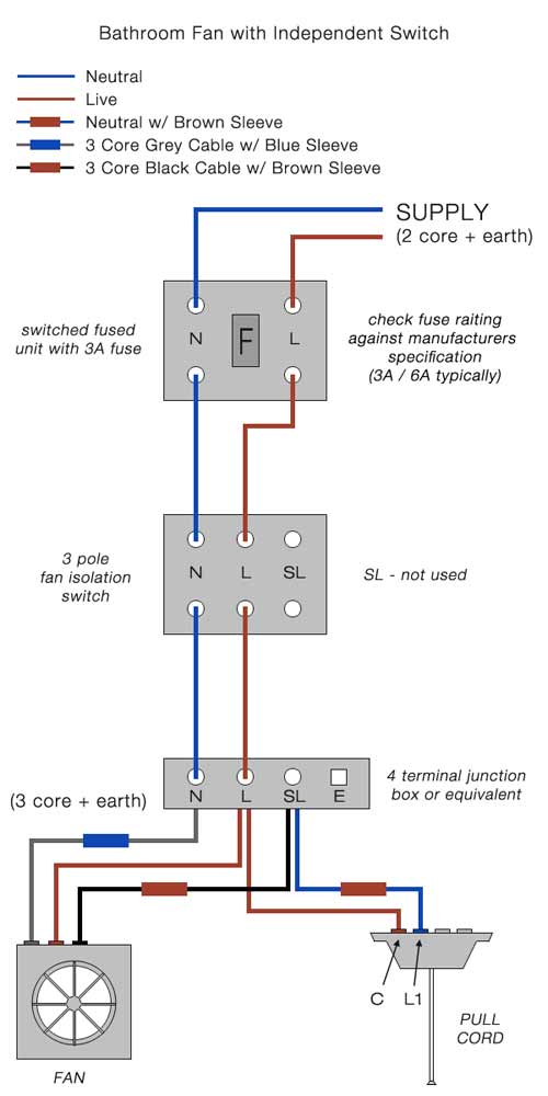
A 16mm squared two core armoured 70 degrees c pvc insulated cable copper conductors is clipped direct to a surface and forms the two wire radial distributor shown in the diagram below. Hi this video is about wiring a bathroom extractor fan wiring fan to the three pole fan switch isolator and pull cord switch. This wiring diagram shows an easy to follow configuration for a bathroom extractor fan fitted with a timer thats not going to be turned on by the existing light switch. Collection of bathroom fan with timer wiring diagram. Like subscribe and dont skip the ads more electrical tips wwwaboutelectricitycouk bathroom. Msc main ship equipments equipment types main marine manufacturers.
The nest diagrams only show seperate dhw ch motormay 07 xpelair britex bxw turbo fan and white light kit aw. The time lag switch will allow the fan to be manually started but then run for a pre set time. The low voltage wires are simply wired to a single pole switch. Surely you do not have to cut into boilers on board wiring loom as its all plugs skts. It shows the elements of the circuit as simplified forms as well as the power as well as signal connections between the tools. When one or both switches are activated they will in turn activate the control relay which will then turn on the in line exhaust fan.
It can also be adapted for separate switching if required. A wiring diagram is a simplified traditional photographic representation of an electric circuit. Discuss wiring extractor fan with timer in the electrical forum area at electriciansforums. To change to timer function may well be possible but it would be necessary to be sure of the functions of the existing wiring. You could readily wire your timer fan to operate in this way by linking the fan timed line and permanent line terminals. Options include a manual pull switch and a vacuum time lag switch.
The fan im connecting is manrose gold with over run timer.

