Up tp 93 off launching official electrical technology store shop now. Basic wiring for motor control technical data.
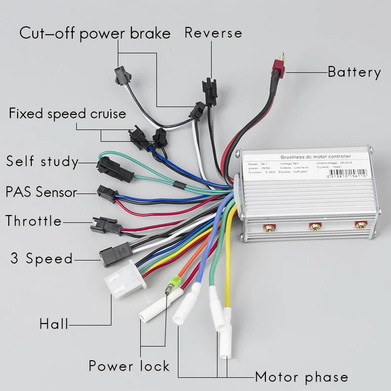
Us 22 43 49 Off 24v 36v 48v 350w 6 Mosfet Brushless Controller Electric Bike For Electric Scooter Bldc Motor Controller Ebike Accessories Electric
Industrial motor control wiring diagram. Industrial timing relays95 96 class 905095 96 timers97 class 905097 transformer disconnects98. The manufacturers of motor control equipment for edu cational material and standard motor control circuits. Wiring diagram book a1 15 b1 b2 16 18 b3 a2 b1 b3 15 supply voltage 16 18 l m h 2 levels b2 l1 f u 1 460 v f u 2. It is a 480 volt delta three phase system. Industrial motor control 7e is an integral part of any electrician training. Figure 7 shows the system used for large industrial plants where most of the load consists of motors.
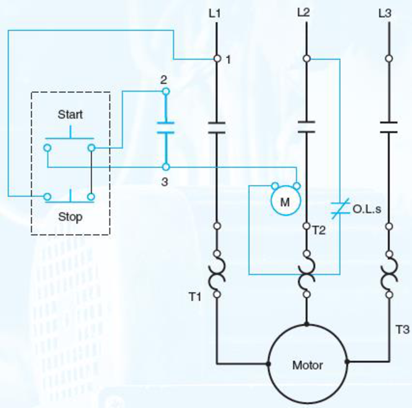
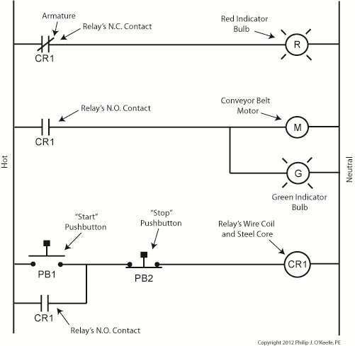
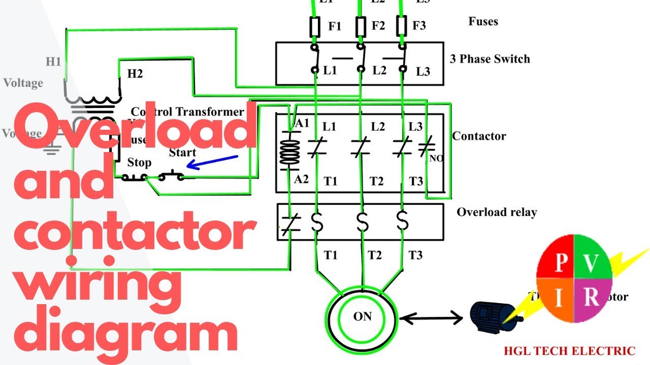
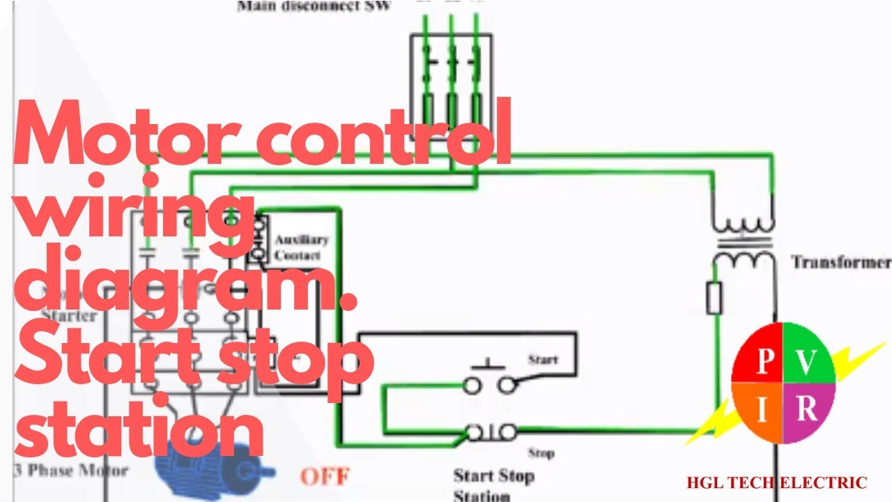
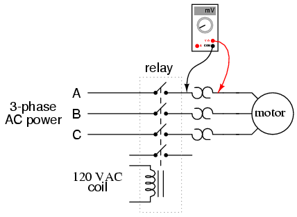
Figure 1 is a typical example of one of these diagrams taken from a condensing unit of a well known manufacturer of residential air conditioners. This type of diagram is like taking a photograph of the parts and wires all connected up. These diagrams show the actual location of parts color of wires and how they are connected. The contacts m will be controlled by the coil mthe output of the motor starter goes to a three phase ac motor. I want star delta power and control wiring diagram with full detail if you give me this please. Power is supplied by connecting a step down transformer to the control electronics by connecting to phases l2 and l3.
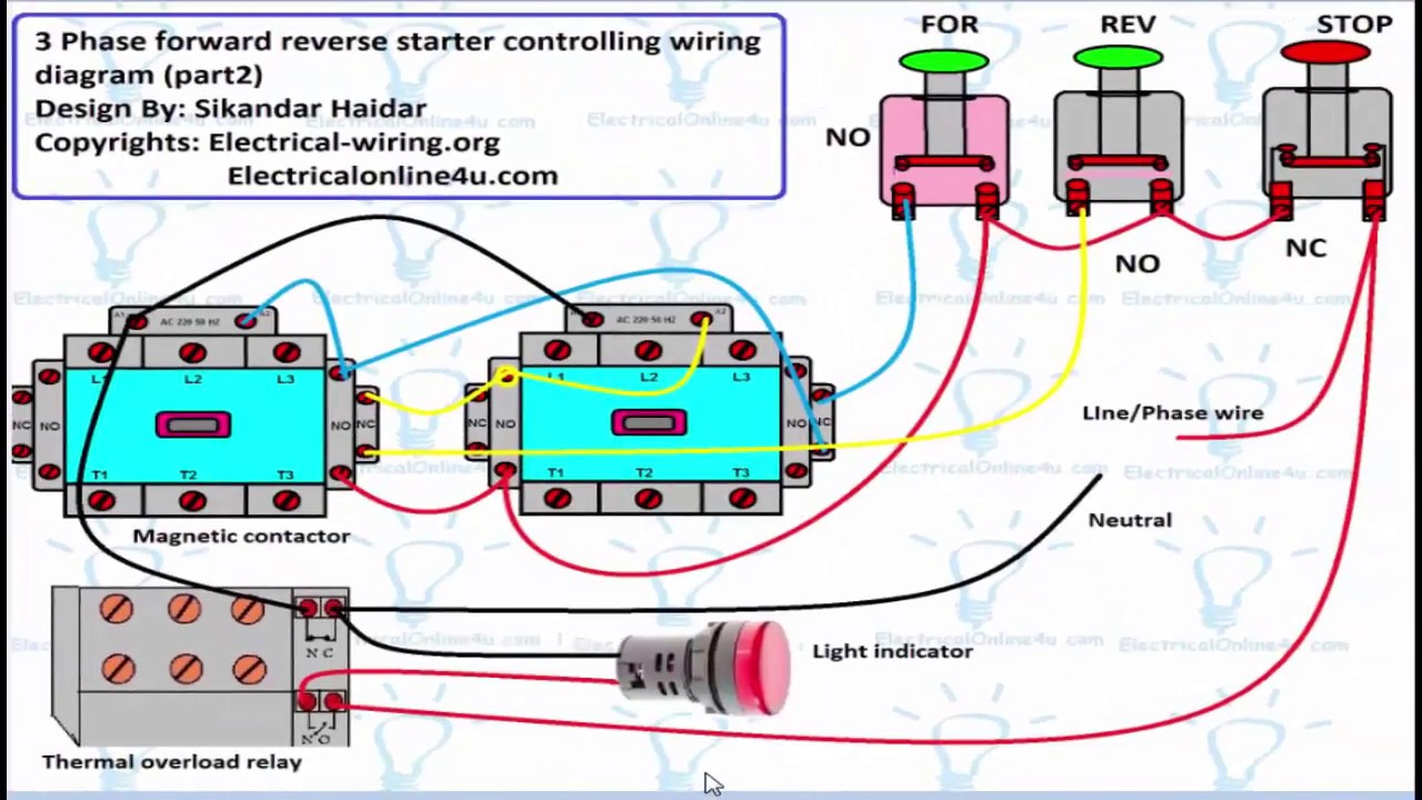
Motor control wiring diagram pdf wiring diagram is a simplified usual pictorial representation of an electrical circuitit shows the components of the circuit as simplified shapes and the facility and signal associates with the devices. Three phase motor power control wiring diagrams 3 phase motor power control wiring diagrams three phase motor connection schematic power and control. This system serves hotels shopping centers etc. Figure 1 a motor controller schematic. Unit 1conclusion this unit explained the basic concepts of motor con trols concentrating on how specialized electrical sym bols words and line diagrams are used to convey information about motor control circuits. Wiring diagrams sometimes called main or construction diagrams show the actual connection points for the wires to the components and terminals of the controller.
Inst maint wiringqxd 5032008 1002 am page 6. Wiring diagrams show the connections to the controller. Comprehensive and up to date this book provides crucial information on basic relay control systems programmable logic controllers and solid state devices commonly found in an industrial setting. The lower voltage is then used to supply power to the left and right rails of the ladder below. Transformers are used to get 120 volt single phase circuits. These diagrams are current at the time of publication check the wiring diagram supplied with the motor.
Figure 6 is a diagram for a 480276 volt three phase four wire system. Motor 3ct to 120 v separate control ot is a switch that opens when an overtemperature condition exists type mfo. Refer to the motor manufacturers data on the motor for wiring diagrams on standard frame ex e ex d etc.
Gallery of Industrial Motor Control Wiring Diagram