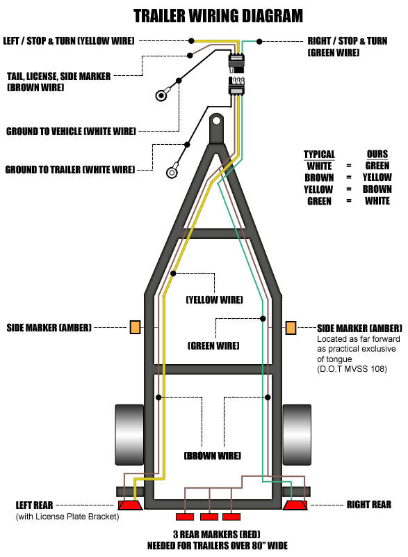
I have attached a helpful article that explains trailer wiring. Lets see what types of connectors the trailer light wiring industry uses today.

Trailer Light Wiring Typical Trailer Light Wiring Diagram
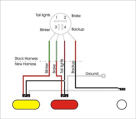
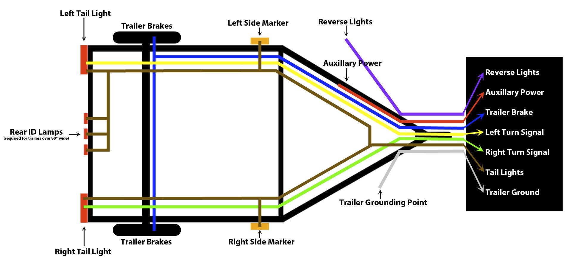
Led trailer tail light wiring diagram. We recommend these standards because they are pretty universal. With all the aid of the guide you are able to very easily do your own wiring assignments. Though trailer lighting systems are available in an array of configurations the most popular is the 4 way system. The following trailer wiring diagrams and explanations are a cross between an electrical schematic and wiring on a trailer. That said for specific situations there are industrial standards with different connectors and wire arrangements. You are able to usually count on wiring diagram being an important reference that may help you conserve time and cash.
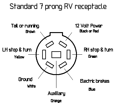
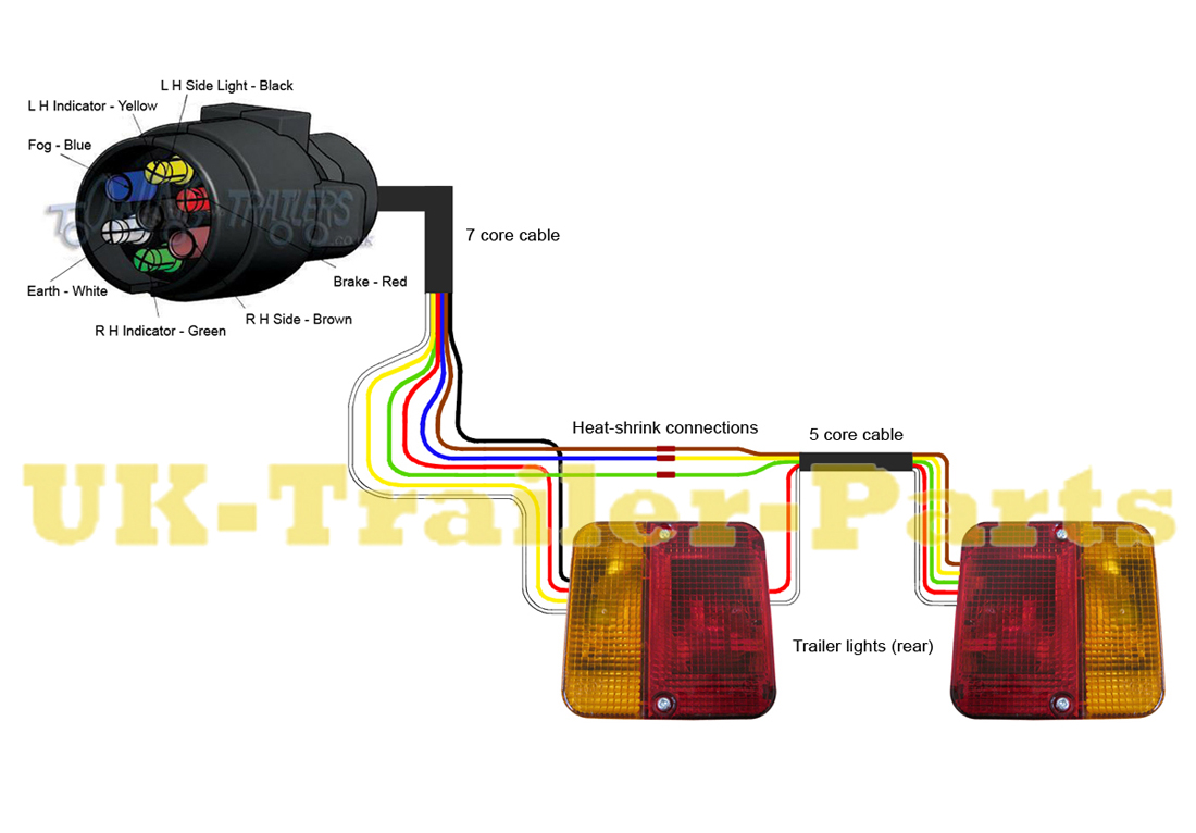
While the basic configuration is a 4 way flat connector that features one female and three male ends you may come across connectors with up to seven pins for additional functions that require wiring including electrically actuated brakes power source for a winch etc. If you have a separate wiring system on your vehicle you can use part rm 732 which will take the separate wiring and convert it to a 2 wire system needed for the led lights and pigtail. It is referred to as such as the system needs a mere four wires for the trailer tail lights turn signals and brake lights to illuminate. Motorcycle led tail light wiring diagram for harley wiring diagram led tail lights wiring diagram. The 4 way system is designed so the right brake light wire and right turn signal are green.
