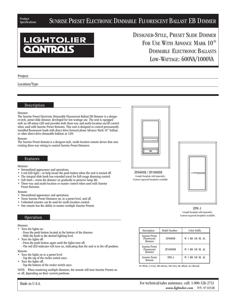
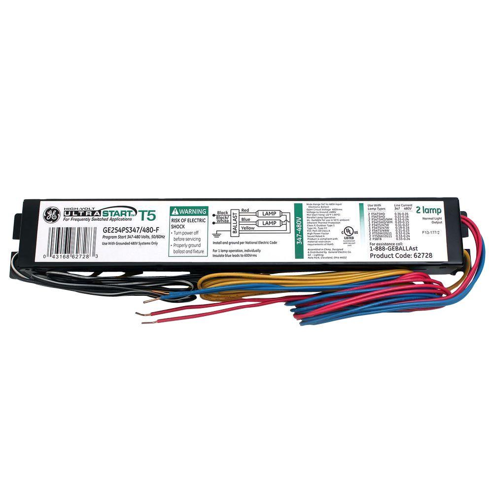
Advance ballast mark 10 wiring diagram 0 10v dimming ballast 08 power factor 09 total harmonic distortion 10 ballast lifetime 11 mounting and grounding 13 sockets and lampholders 16 lamp wiring diagrams 19 ballast control types 20 ecosystem ballasts 22 emergency backup ballast. If the light output can only be dimmed from 100 down to 10 there must be a switch or relay available to kill power to the system and turn the light.

Mark 7 Ballast Wiring Diagram Wiring Diagrams
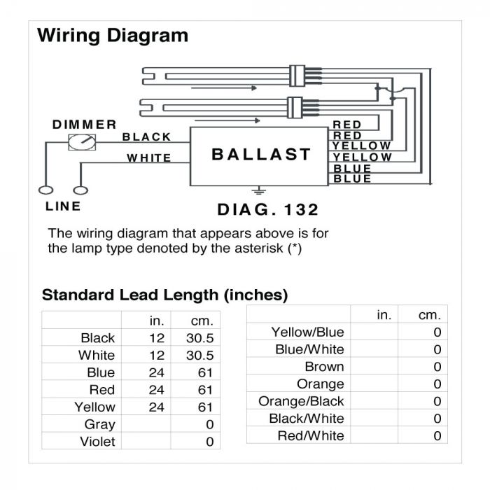
Mark 10 dimming ballast wiring diagram. The mark 7 010v series of dimmable electronic ballasts offer maximum versatility by incorporating separate control leads for use with a wide array of controllers. Amazing dimmer switch circuit diagram best for. In many cases the dimming range of the power supply or ballast is limited. Dimming ballasts are available for fluorescent tubes and cfls that use an external ballast. Advances mark 7 v ballasts are 5 full range continuous dimming t5ho to 1 for ballast dimensions and wiring diagrams see page 3. Dimming fluorescent lights are usually found in commercial and institutional environments and not common in the household.
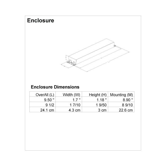
Wiring diagram 40 best advance mark 7 dimming ballast wiring. These ballasts are usually rapid start or programmed start and have a good dimming range. 0 10v dimming ballast wiring diagram collections of 0 10v dimming ballast wiring diagram sample. Mark 10 powerline ballasts for linear 5 full range continuous dimming t5ho to 1 for ballast dimensions and wiring diagrams see page 5. Advance dimming ballast wiring diagram. Often dimming ballasts and dimming led power supplies use 0 10v control signals to control dimming functions.
Lamp dimming ballast wiring diagram get free image about wiring. Changing the wiring on a.


