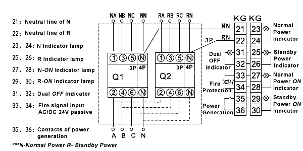
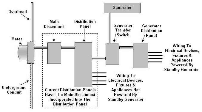
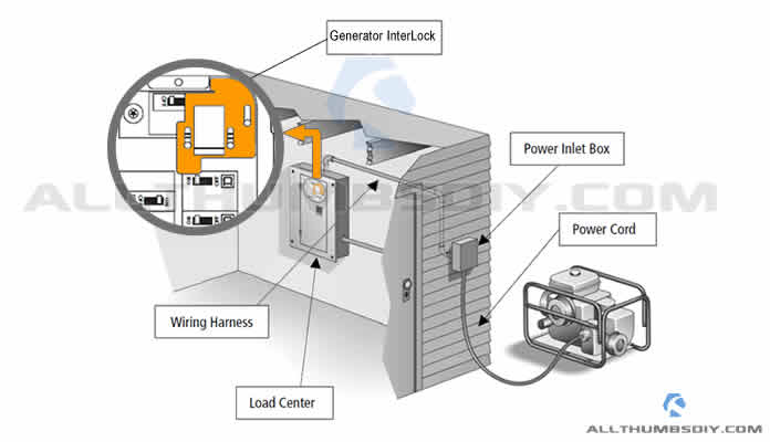
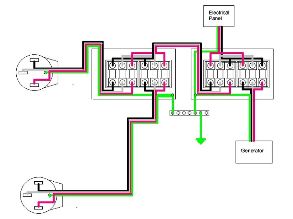
Figure 4 wiring diagram of a manual transfer switch in the off position figure 5 wiring diagram of a manual transfer switch in the on position when utility power is functioning the wires from the circuit breaker in the main electrical distribution panel are connected to the generator sub panel. Wiring diagram asco series 300 group g automatic service entrance transfer switch atsntsaus 30 230 amps frame d three phase 978741 document number ts wd 300dats978741.

Wiring Diagram Changeover Switch Generator
Power transfer switch wiring diagram. In our step by step electrical wiring installation tutorials series we will show how to wire and connect single phase and three phase automatic and manual changeover and transfer switches to the home distribution board to use the backup power supply such us batteries power with ups and inverters or generator power in case of emergency breakdown and power outage. This task requires experience with electrical wiring. It reveals the components of the circuit as streamlined forms and also the power as well as signal connections in between the gadgets. Assortment of manual transfer switch wiring diagram. A wiring diagram is a simplified traditional pictorial representation of an electrical circuit. Installing a transfer switch refers to the process of adding the necessary trigger to change your energy to generator power in the event of an electrical outage.
Because the amount of electricity created by a backup generator is not adequate to power all of the electrical circuits in your house youll need to designate a few selected circuits to get backup. Follow these steps for. Manual transfer switches require an operator to change the power source while automatic switches detect the loss of power start the back up generator and switch over to the backup power feed.

