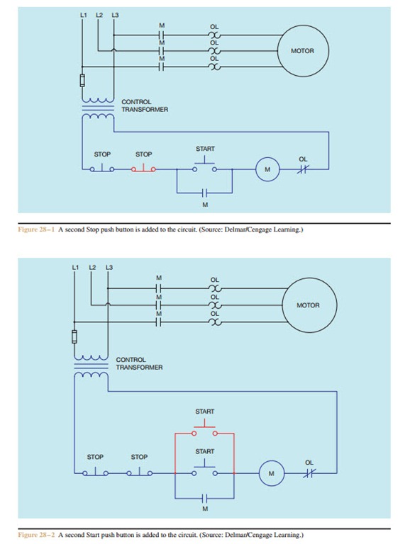
With the motor running contacts are open. This video builds on the standard 3 wire circuit by incorporating multiple stopstart stations.
Solved The Hardwired Multiple Start Stop Motor Control Ci
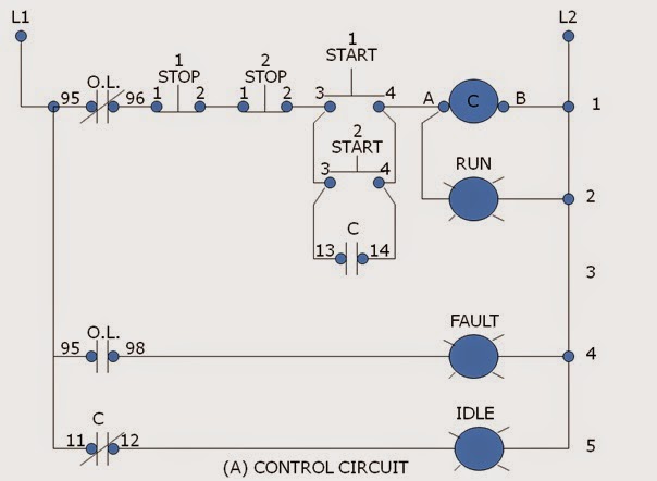
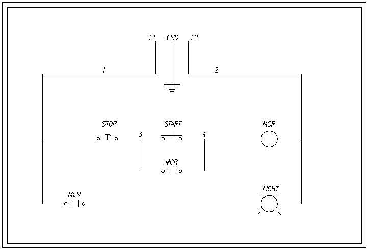
Schematic diagram of start stop motor control. Pilot light l2 4 2 3 pilot light start stop bulletin 1495 normally closed auxiliary contacts are required. Although this diagram looks completely different it is electrically the same as the schematic diagram. In this convention the hot. Notice the push button symbols indicate double acting push buttons. Question 19 an alternative to the conventional schematic diagram in ac power control systems is the ladder diagram. Typical line or schematic diagram t3 95 reset 96 l2 t2 l1 1 3 2 t1 97 98 3 2 1 m ol 3 phase motor start stop a1 a2 l3 t3 95 ol ol ol ol 96 l2 t2 l1 1 2 3 t1 ac lines m m m m m motor start stop a1 a2.
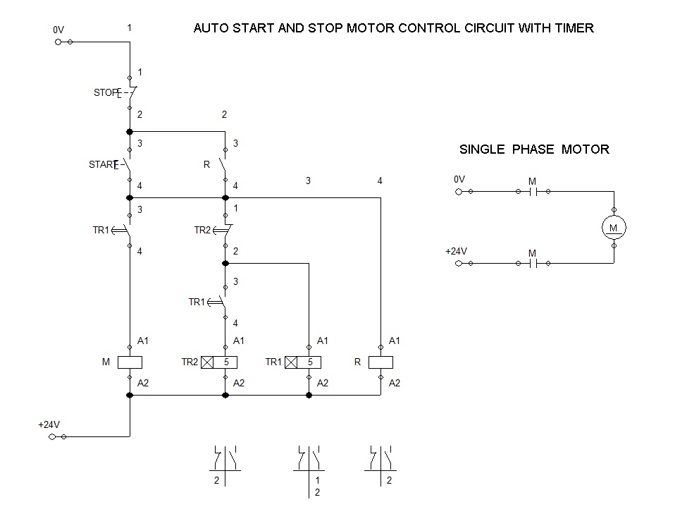
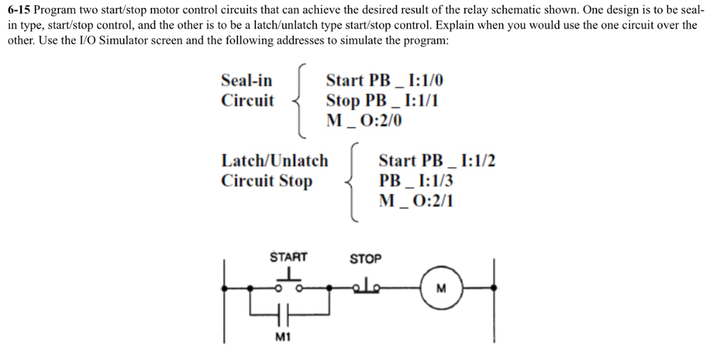
It uses three contactors an overload relay one auxiliary contact block a normally open start pushbutton a normally closed stop pushbutton an on delay timer of 0 20 seconds and a power supply with a fuse. The basic language of control is the circuit diagram. Td03309004e for more. For push button control stations 7 start stop control wiring diagrams single station with motor stopped pilot light l1 start l2 i 1 stop 2 oi 3 n wol. C i m nc. A wiring diagram for the start stop pushbutton circuit is shown in figure 917.
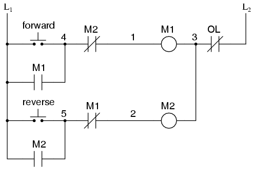
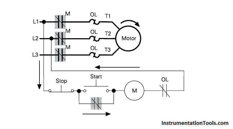
See image below for an example of 3 wire control being used to pull in a contactor to start a 3 phase motor. The following diagram is shown for 3 phase motor control of a delta star connection. The most common use of 3 wire control is a startstop control. Wye delta open transition 3 phase motors. Undervoltage protection and three wrre control should brmg to mrnd a start stop push button staton whrch the most common means of provrdrng this type control. When you press the start button and the stop button is not pressed the 24vdc relay energizes and it pulls in the r1 contactor that feeds three phase power to the motor.
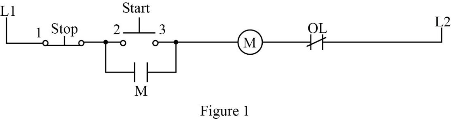
With the switch closed the control circuit acts as a normal stopstart station controlling a load connected to the pilot device power is sitting on the start and seal in terminals of the pushbutton. L3 t3 t three wires three wjfes lead from the plot devtce to thestarter. Start stop 3 wire control. Motor starter schematic and wiring diagram. Ladder diagram basics 3c 3 wire control duration. Ask your students if they can think of any application for a circuit such as this.
Motor start stop circuits are very common in industry and apply to applications beyond electric motors. Shows a typical line or schematic diagram. Starting a three phase motor. Control circuit until the start button is pressed once again. T w 6. Pressing start immediately sends power through the start pushbutton and the seal in contacting energizing the coil.
Gallery of Schematic Diagram Of Start Stop Motor Control