The generation voltage is usually 11kv and 33 kv. With capacitor marking and installation.

Engineering Principles And Applications Of Electrical
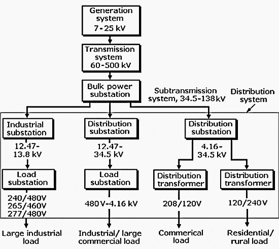
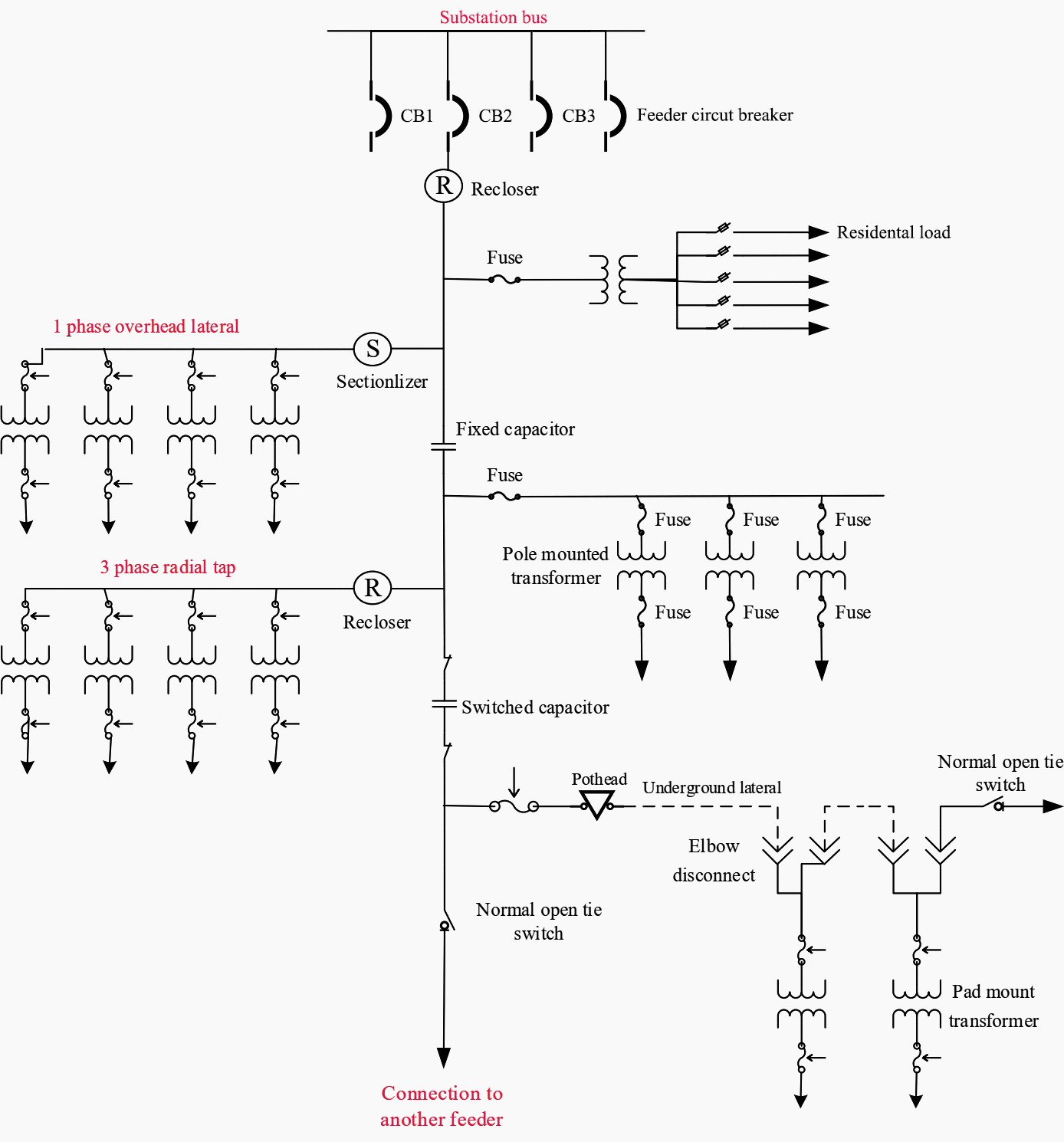
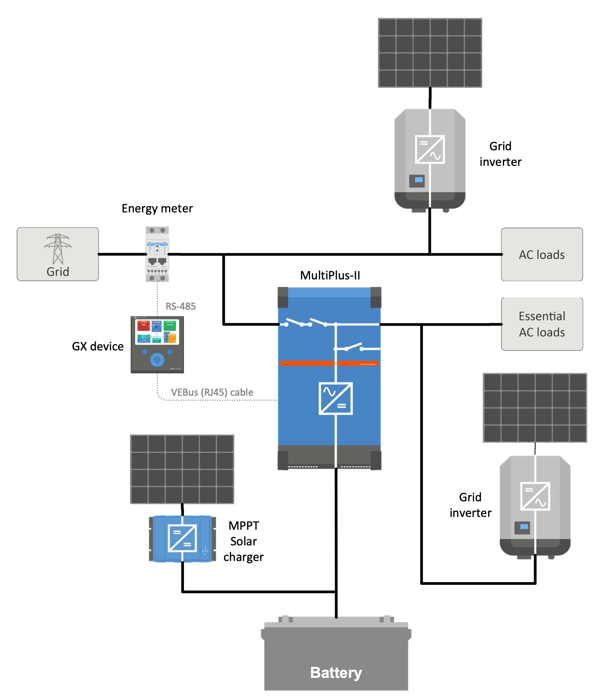
Simple layout diagram of electrical energy from generation to distribution. Without going into great detail i thought that i would illustrate a very simple and basic solar power system diagram. The one line diagram shows a simplified arrangement of the primary electrical components. The conventional simple radial system receives power at the utility supply voltage at a single substation and steps the voltage down to the utilization level. Apart from varying demand the type of current we consume also varies. Room air cooler wiring diagram 2. Electrical wiring of the distribution board with rcd single phase from energy meter to the main distribution board fuse board connection.
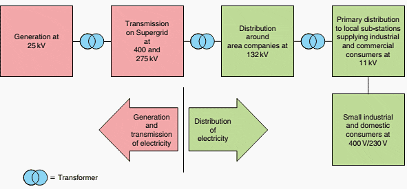
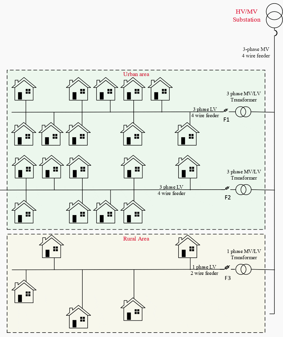
Figure 1 single line diagram of transmission and distribution network. Voltage levels of 132 110 in some places or 66 kv are usual hv levels that can be found in european distribution networks. Heres a simple small 300 watt solar panel system with a 600 watt dc ac inverter just for an example. A more detailed discussion of each component follows this narrative. In addition our demand is always varying. Electricity is generated at power plants and moves through a complex system sometimes called the grid of electricity substations transformers and power lines that connect electricity producers and consumersmost local grids are interconnected for reliability and commercial purposes forming larger more dependable networks.
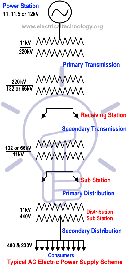
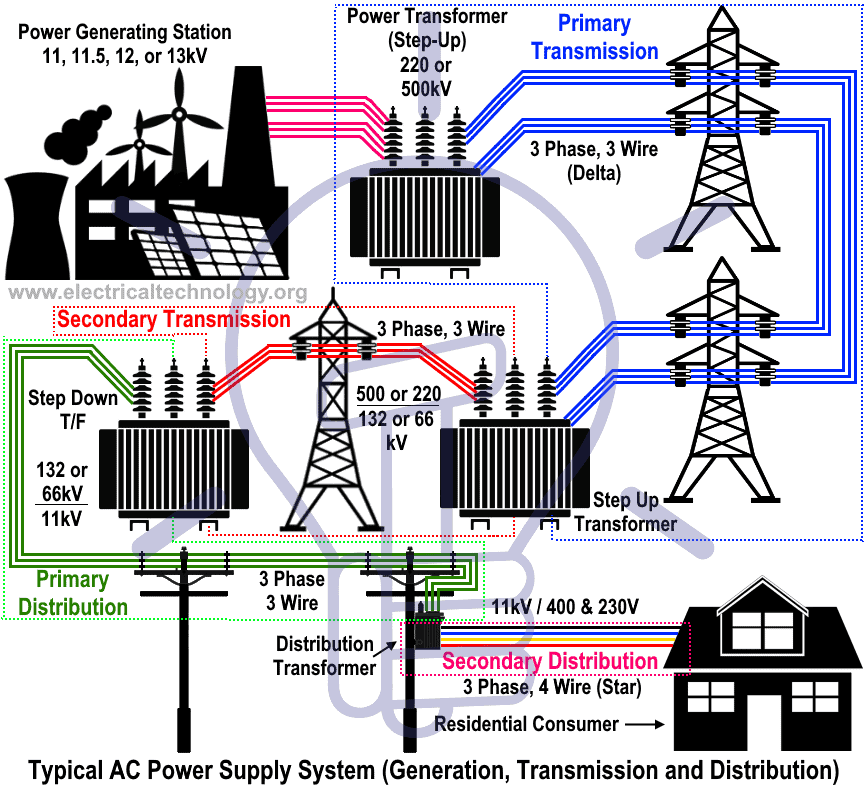
In figure 1 cs. The voltage is then stepped up by suitable 3 phase transformers for transmission purposes. Central station where power is generated by 3 phase alternators. You could utilize 3 100 watt panels listed below. The output of the. Therefore the generation is also varying with it.
Room air cooler electrical wiring diagram 1. Power system restoration outage voltage collapse switching programs therefore the generation of electrical energy is happening simultaneously as we use it. Represents the central station where power is generated by 3 phase alternators at 66kv or 11kv or 132kv or even 32 kv. Distribution segment is widely recognized as the most challenging part of the smart grid due to its ubiquity. The high voltage is required for long distance transmission and the low voltage is required for utility purposes. Voltages below that eg 30 20 10 kv are commonly found in mv distribution networks.
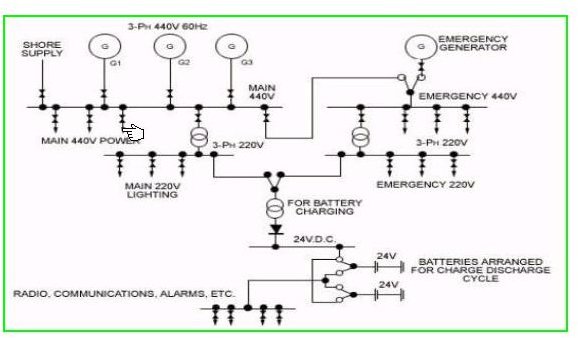
Electricity is delivered to consumers through a complex network. With the simple radial system the loss of the utility source transformer or the service or distribution equipment will result in a loss of service. According to the specs of these particular panels the combined. The voltage level is going on decreasing from the transmission system to the distribution systemthe electrical energy is generated by the three phase synchronous generator alternators as shown in the figure below. Starting at the upper left corner of the diagram a circle symbol with a y in the center represents the plant main electrical generator.
