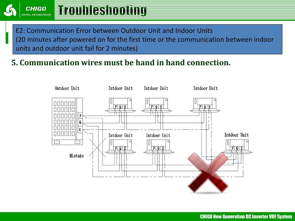
Units are connected through copper tubing and electrical cabling. Variable refrigerant flow vrf system single phase outdoor unit series models.

Vrf Hvac Systems Advent Air Conditioning
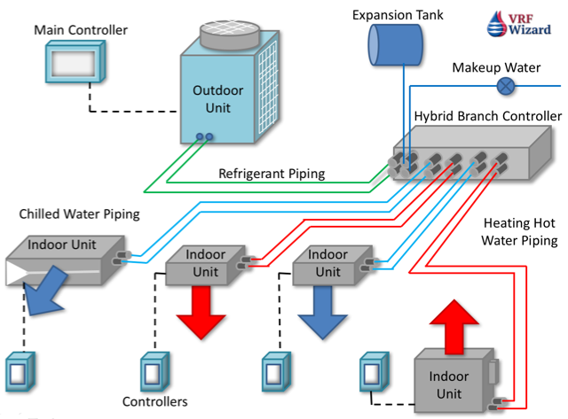
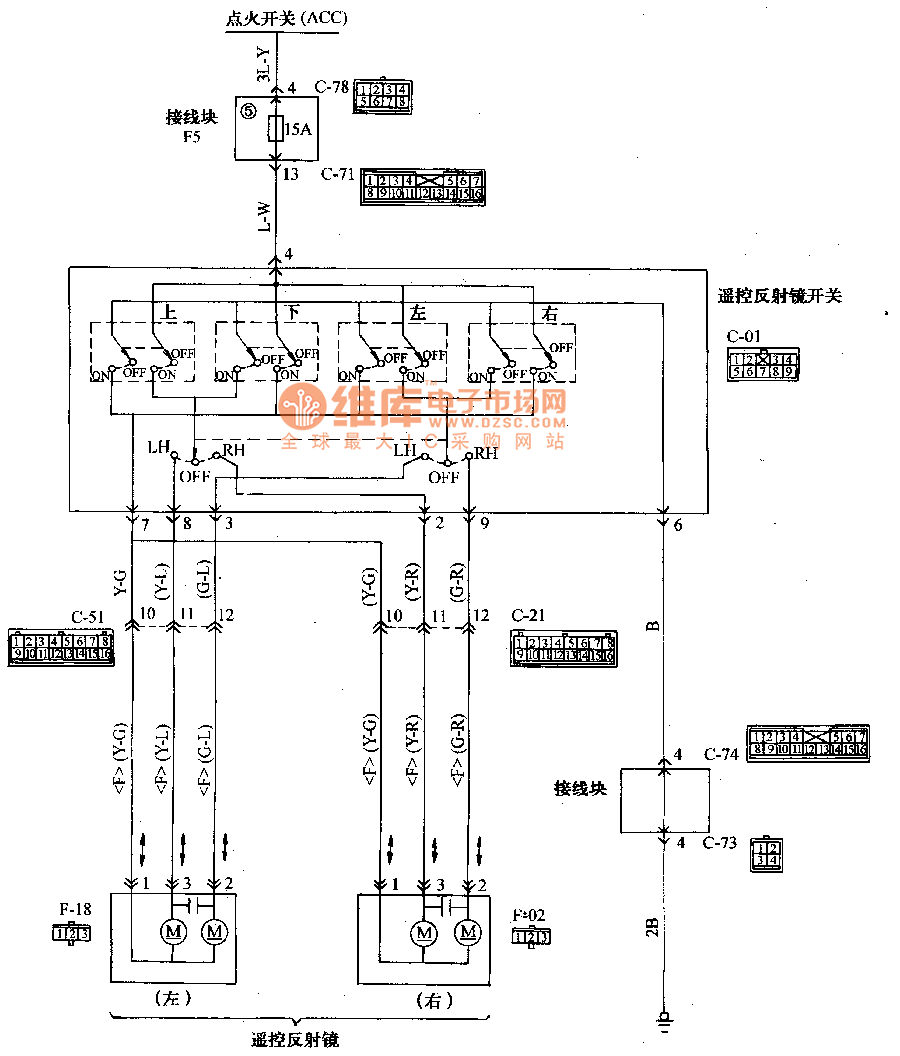
Vrf electrical diagram. Secondly is about the recommend. Performance rating of variable refrigerant flow multi split air conditioning and heat pump equipment ieer has been established as a measure of the cooling produced for the amount of energy required to produce it in btu per watt per hour. This vrf system control wiring is for a vrf vrv heat recovery system with single port branch selector boxes. Variable refrigerant flow vrf is an air condition system configuration where there is one outdoor condensing unit and multiple indoor units. What is a variable refrigerant flow vrf air conditioning system. Vrf system control wiring.
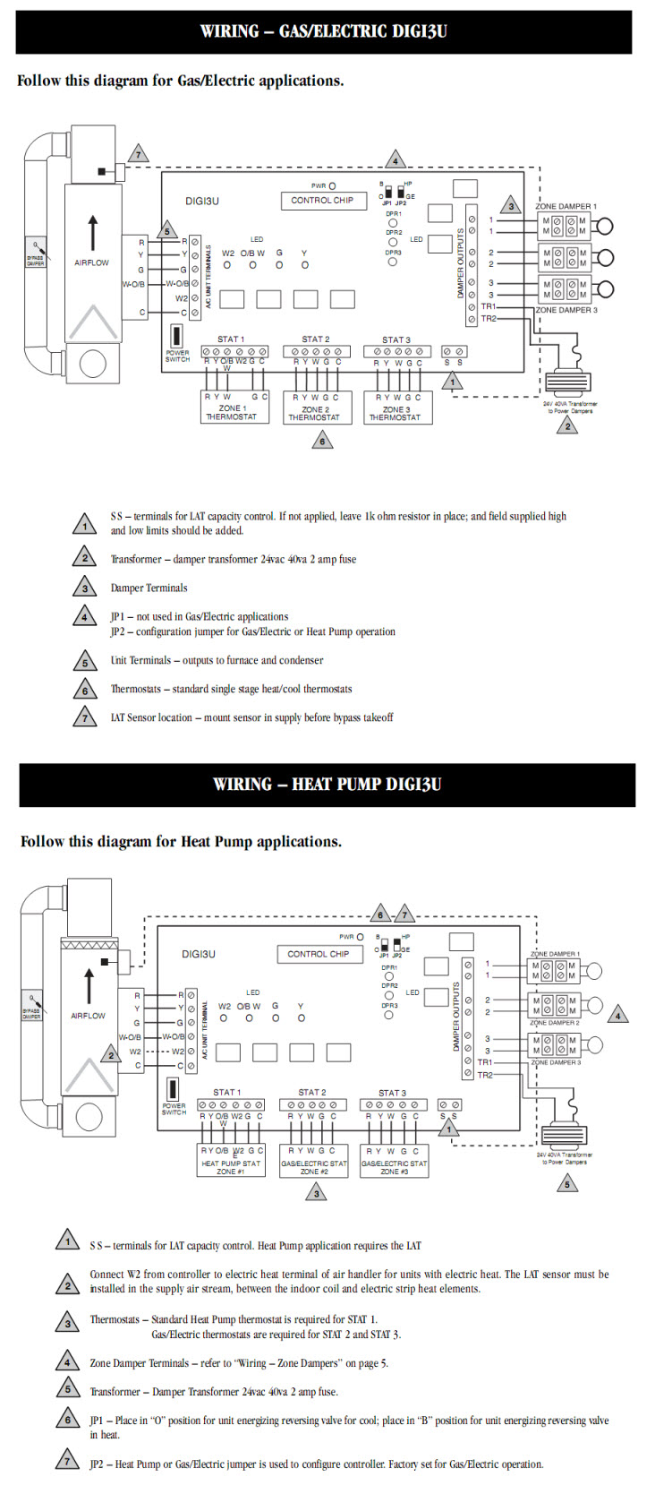
The indoor part evaporator pulls heat out from the surrounding air while the outdoor. The control wiring is very simple its basically two 18 gauge wires that go from the thermostat to the fan coils wire 1 so that each zone will have a wire from the thermostat to the fan coilone controller thermostat can control more than one indoor. Failure to follow code could result in death or serious injury. First of all i talking about the previous review with the whole system. In this video i am going to show you how panasonic fsv vrf system wiring connection digram. 4tvh0036b100nc 4tvh0048b100nc 4tvh0053b100nc.
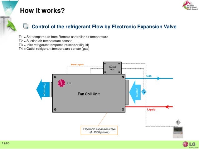
The term variable refrigerant flow. The term variable refrigerant flow refers to the ability of the system to control the amount of refrigerant flowing to each of the evaporators enabling the use of many evaporators of differing capacities and configurations individualized comfort control simultaneous heating and. Heres the definition according to ashrae. Integrated energy efficiency ratio ieer per air conditioning heating and refrigeration institutes ahri standard ahri 1230. Wiring installation and grounding as described in nec and your localstate electrical codes.


