When regulated 5v is connected. Using this simple wireless switch circuit you can avoid the dangers of having physical contact with the switches.

Two Way Switching Wiring Diagram In Two Way Switch Wiring
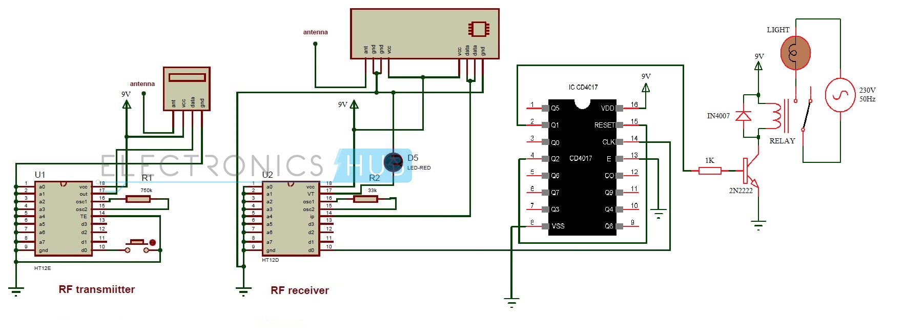
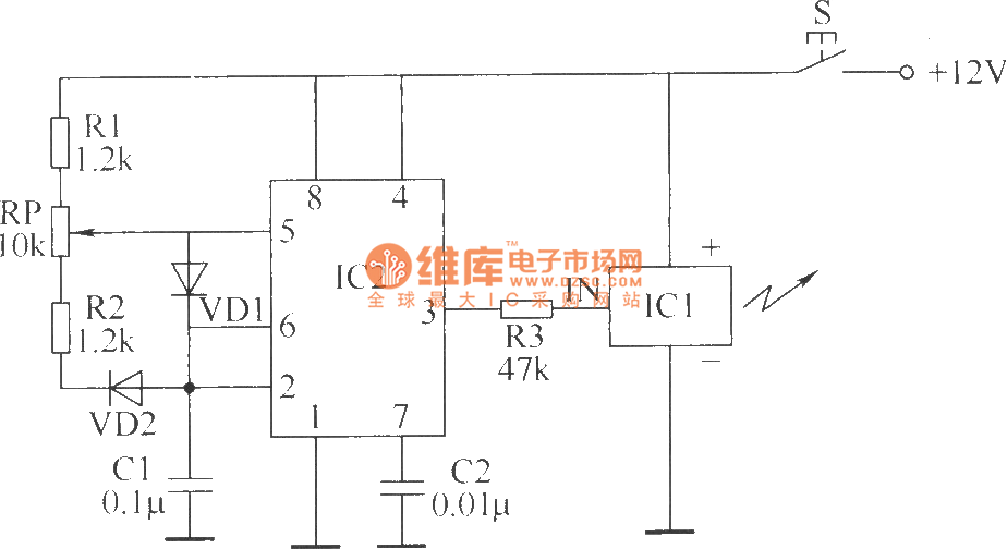
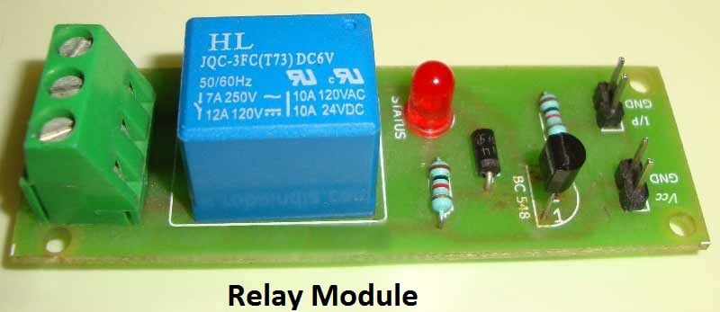
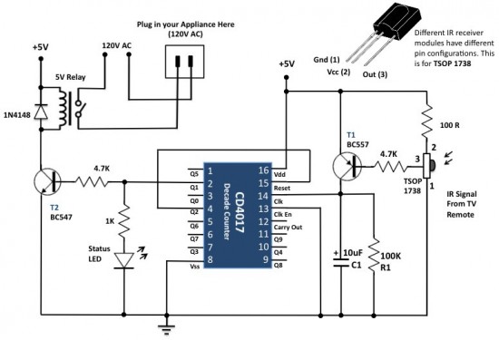
Wireless light switch circuit diagram. Ir infrared remote controlled switch circuit diagram for lightfan appliance. It is simple compact and cheap. It is simple compact and cheap. A relay switch is used at the output of the circuit which can be connected with the appliances to make them switch onoff. This home made wireless remote controlled switch system is a very easy to construct and can change our living experiance. Current consumption is low in milliamperes.
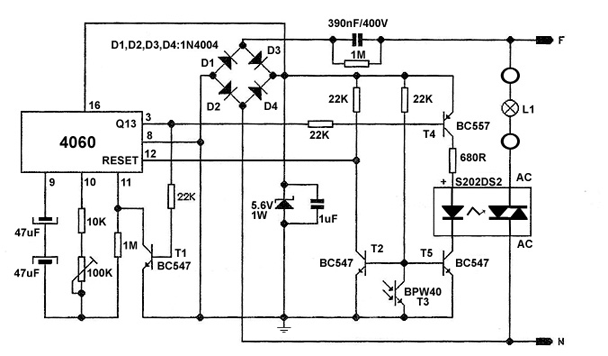
Current consumption is low in milliamperes. In this project we are going to show you how to make a wireless circuit using ldr lm741op amp ic and 4017 decade counter ic. This circuit is very stable and sensitive compared to other ac appliance control circuits. For good results use a good quality fm transmitter with the circuit. The whole project contains two parts which is an fm transmitter and a rf receiver. The method implemented here involves a wireless switch circuit where when you slide our hand in front of the circuit the device like lamp will be turned on and if you slide you hand once again the device will be turned off.
The circuit has also a good range of upto 20 meters. This wireless light switch is very stable and sensitive compared to other ac appliance control circuits. So today we are building a simple wireless switch circuit in which there is no need of physical contact with the switch just one has to take his hand over the switch and it turns onoff the light. This is a good solution for a unique and so interesting idea to wireless switching system to control the home appliance. The circuit is built around an ic ca3140 irled1 phototransistor and other discrete components. The circuit is built around an ic ca3140 irled1 photo transistor and other discrete components.
The working of the circuit is simple.




.gif)


