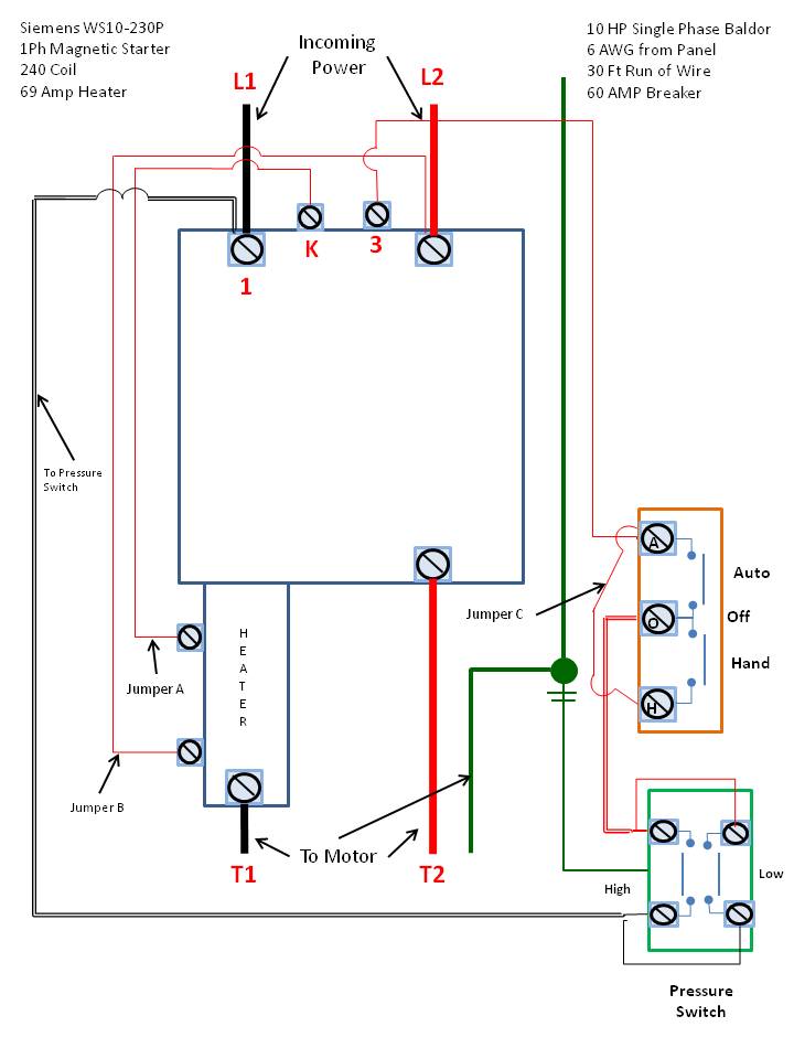
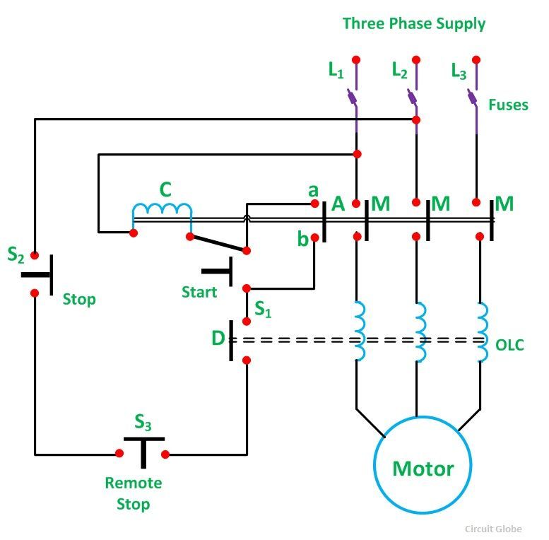
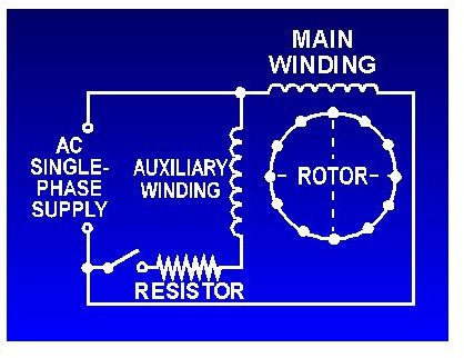
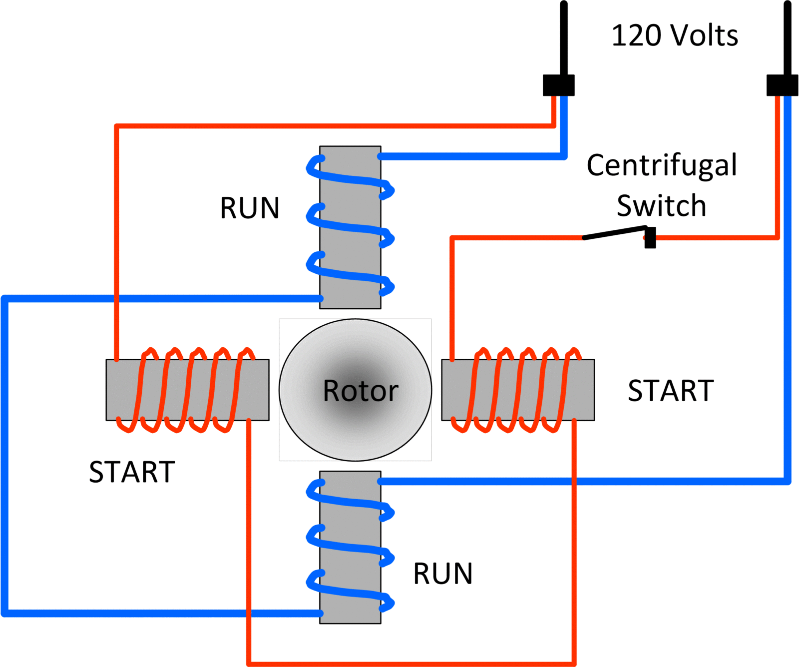
Click here to view a capacitor start motor circuit diagram for starting a single phase motor. If you have a 120v coil instead of running a line from coil overload l2 you must run coil overload neutral.

10 Electric Motor Starter Wiring Diagram Wiring Diagram In
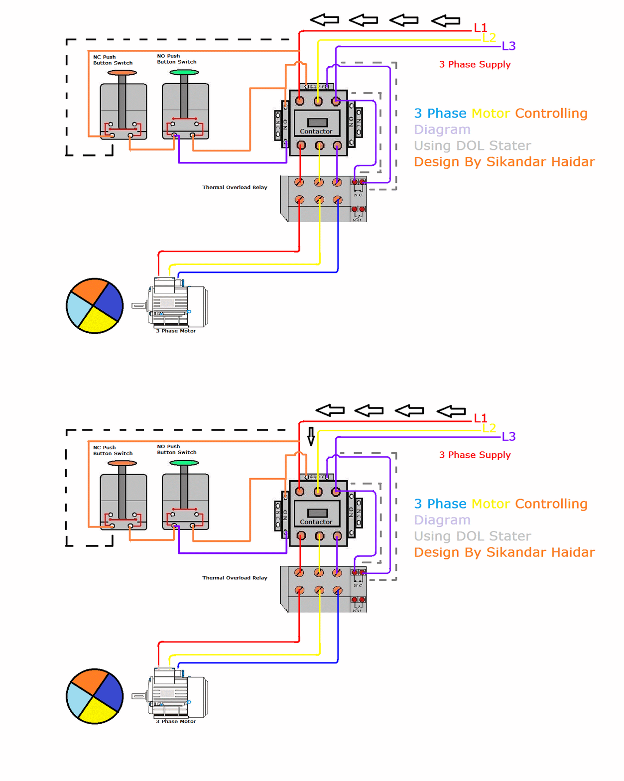
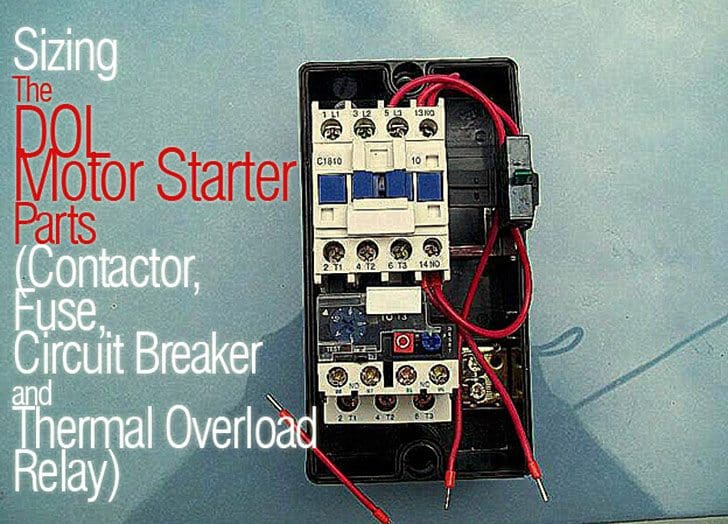
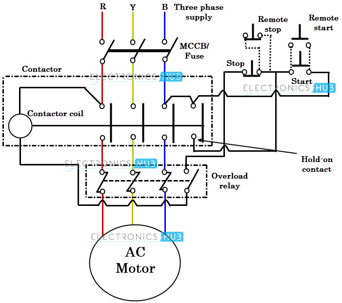
Wiring diagram for single phase motor starter. Or by calling 888 226 4917. The control wiring will be as that for the 240vac coil version of the 3 phase system. Wiring a single phase motor through a 3 phase contactor. The above diagram is a complete method of single phase motor wiring with circuit breaker and contactor. Also read about the speed torque characteristics of these motors along with its different types. Types of single phase induction motors electrical a2z single phase induction motors are traditionally used in residential applications such as ceiling fans air conditioners washing machines and refrigerators single phase motor wiring with contactor diagram the plete guide of single phase motor wiring with circuit breaker and contactor diagram.
In the above one phase motor wiring i first connect a 2 pole circuit breaker and after that i connect the supply to motor starter and then i do cont actor coil wiring with normally close push button switch and normally open push button switch and in last i do connection between capacitor. Single phase power is typically reserved for lower power requirements however in some cases powering a small motor with single phase input power is practical. Posted january 18 2018 by springercontrols. I hope after watching the above single phase submersible pump starter wiring diagram guide video tutorial i hope now you will fully understood the complete submersible pump control starter wiring diagram or installation and now you will be able to wire or make your own submersible pump motor starter however now if you have any question regarding the video tutorial or diagram then you can ask. Single phase motor wiring diagram with capacitor start. Properly connect a single phase motors to a three phase starter.
It reveals the parts of the circuit as simplified shapes and the power and signal links between the gadgets. Please see the attached diagram for guidance. Wondering how a capacitor can be used to start a single phase motor. Home about us news wiring a single phase motor through a 3 phase contactor. This diagram illustrates possible wiring using a tesys d lc1d contactor and tesys lrd overload lrd. The diagram below shows the wiring for a single phase motor and the path through the contactor and overload.
A wiring diagram is a simplified traditional photographic representation of an electric circuit. Single phase motor wiring diagram with capacitor baldor single phase motor wiring diagram with capacitor single phase fan motor wiring diagram with capacitor single phase motor connection diagram with capacitor every electrical arrangement is made up of various unique pieces. Learn how a capacitor start induction run motor is capable of producing twice as much torque of a split phase motor. Line voltage control three phase 3ph motor starter controlling a three phase motor rev 08 aug 2006 the above wiring diagram assumes your magnetic starter has a 240v coil. Collection of single phase motor starter wiring diagram. Each component ought to be placed and linked to different parts in particular manner.
