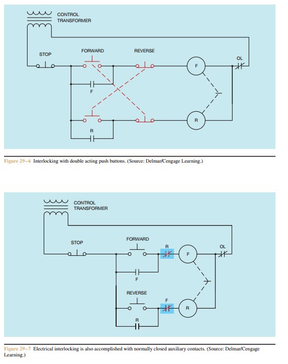
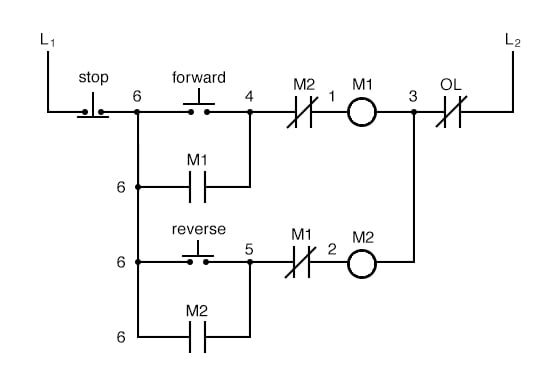
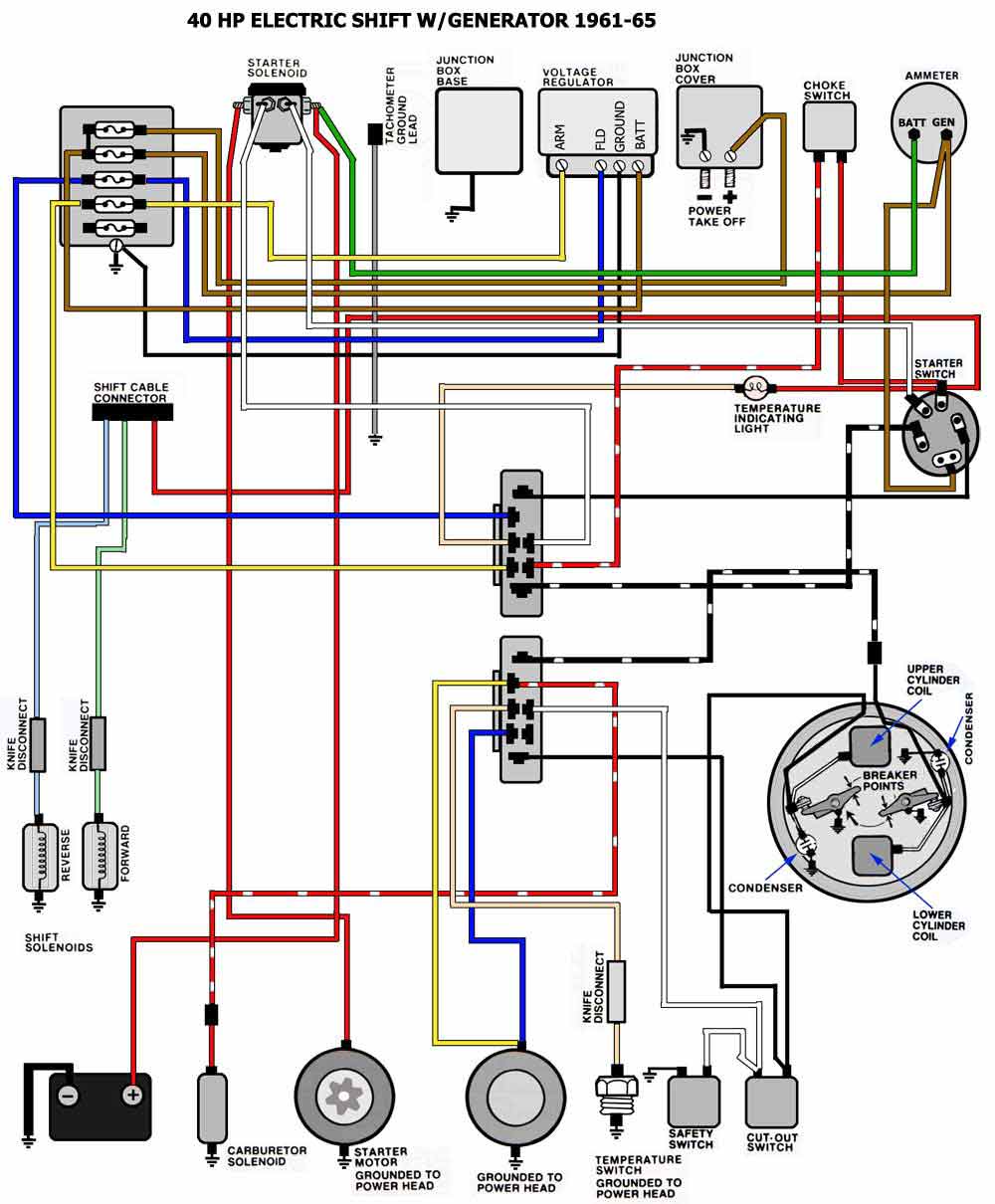
They show the relative location of the components. Inst maint wiringqxd 5032008 1002 am page 6.

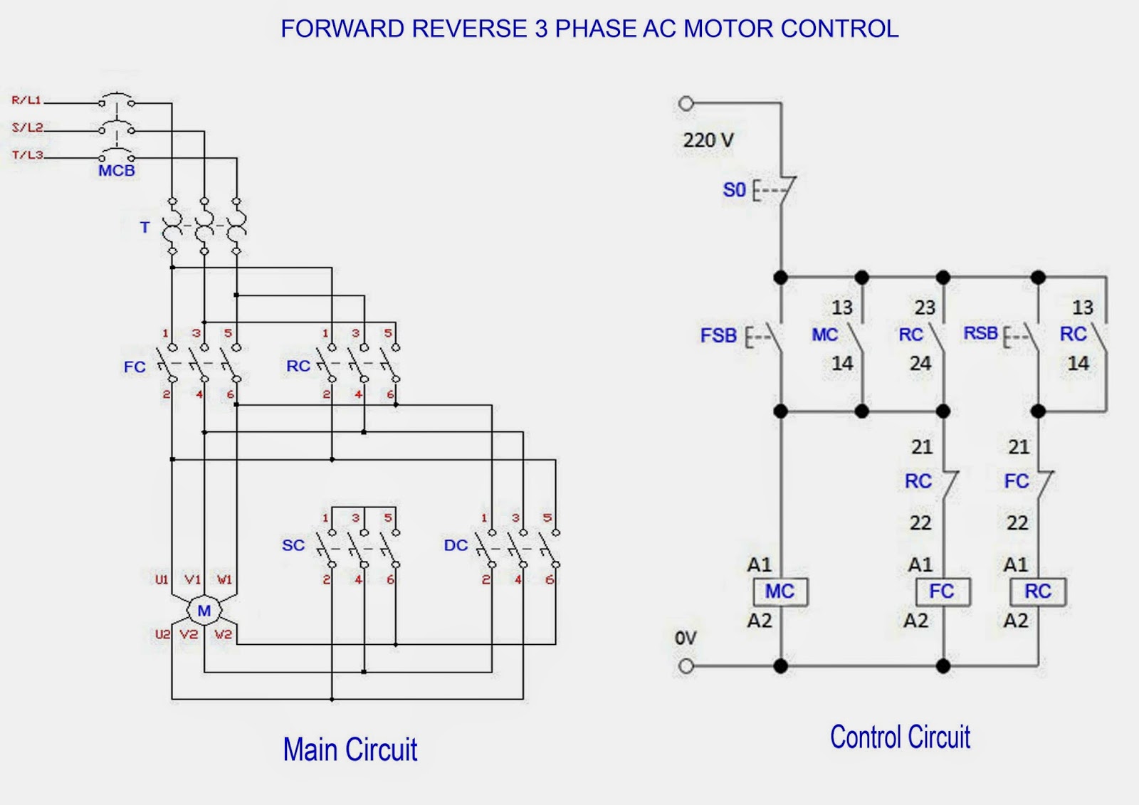
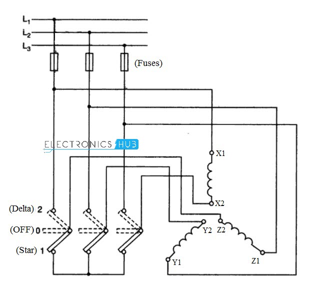
Star Delta Starter For 3 Phase Motor
10 hp motor starter typical wiring diagram. A motor starter is a combination of devices used to start run and stop an ac induction motor based on commands from an operator or a controller. Electrical motor wiring data nema amps starter size hmcp size for motors ranging 12 to 500 hp sponsored links 480 volt motor wiring data national electric manufacturers association nema amps starter size hmcp size overload phase wires gnd and conduit size. Baldor single phase motor wiring diagram collections of weg motor capacitor wiring diagrams schematics and baldor diagram in. They can be used as a guide when wiring the controller. In north america an induction motor will typically operate at 230v or 460v 3 phase 60 hz and has a control voltage of 115 vac or 24 vdc. These diagrams are current at the time of publication check the wiring diagram supplied with the motor.
If you have a 120v coil instead of running a line from coil overload l2 you must run coil overload neutral. Phase 1 l2 l4. Figure 1 is a typical wiring diagram for a three phase magnetic motor starter. Baldor reliance industrial motor wiring diagram new wirh baldor. Electric motor start run capacitor instructions. Typical controller markings typical elementary diagram table 4 control and power connections for across the line starters 600 v or less from nema standard ics 2 321a60 1 phase 2 phase 4 wire 3 phase line markings l1 l2 l1 l3.
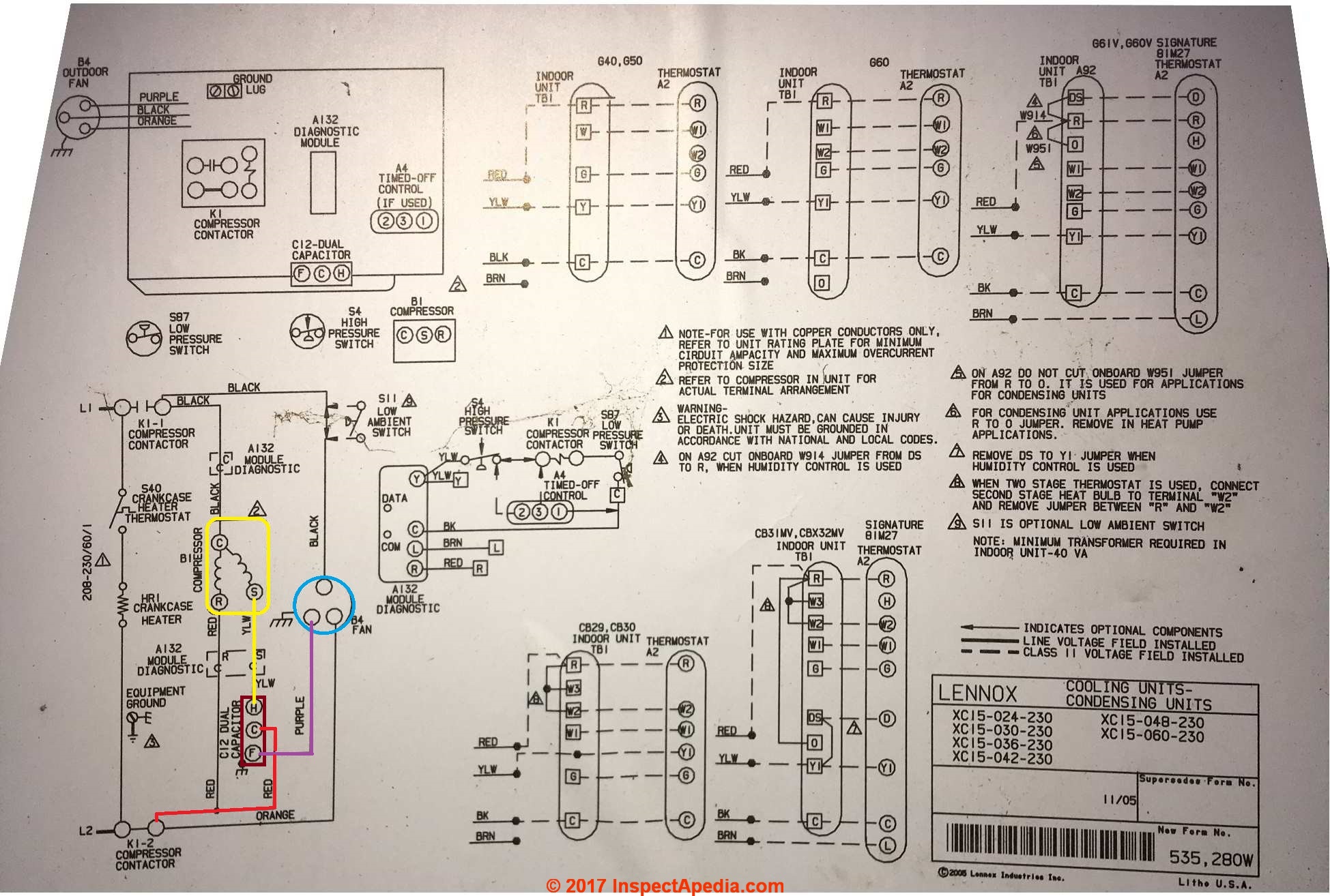
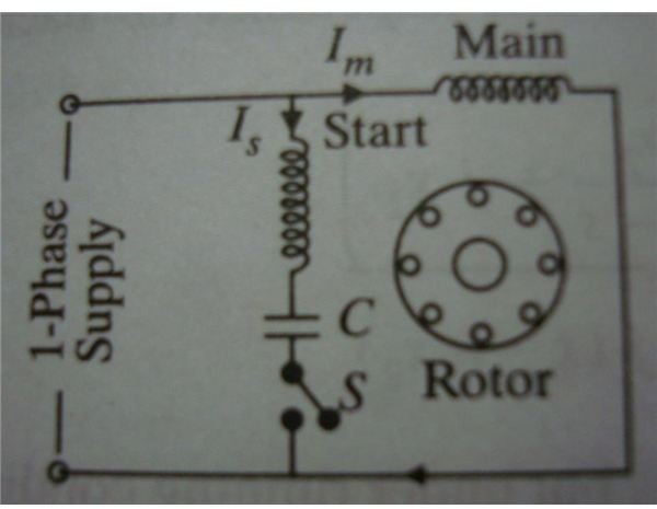
Phase 2 l1 l2 l3 ground when used l1 is always ungrounded l2 motor running overcurrent. Weg motor capacitor wiring diagrams schematics and baldor diagram in. This article gives electric motor start run capacitor installation wiring instructions for electric motor capacitors designed to start run an electric motor such as an ac compressor heat pump compressor or a fan motor and how to wire up a hard starting air conditioner compressor. How to hook up an electric motor start or run capacitor. 3ph starter3ph motor line voltage control three phase 3ph motor starter controlling a three phase motor rev 08 aug 2006 the above wiring diagram assumes your magnetic starter has a 240v coil. Refer to the motor manufacturers data on the motor for wiring diagrams on standard frame ex e ex d etc.
Always use wiring diagram supplied on motor nameplate. 5 hp electric motor single phase wiring diagram beautiful single. Figure 1 typical wiring diagram. Basic wiring for motor control technical data.

