Assortment of 3 phase capacitor bank wiring diagram. Also read about the speed torque characteristics of these motors along with its different types.

Activecap Catalogue
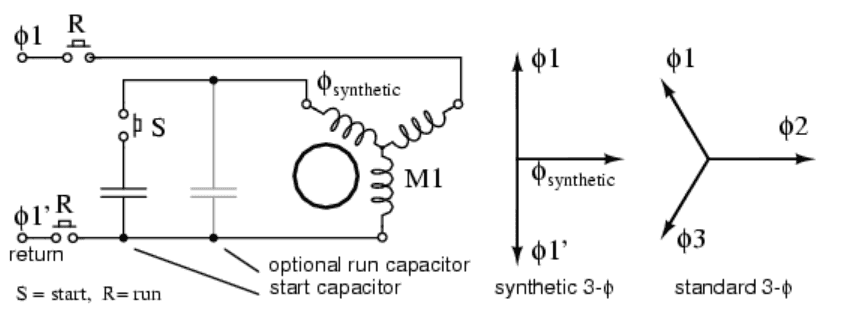
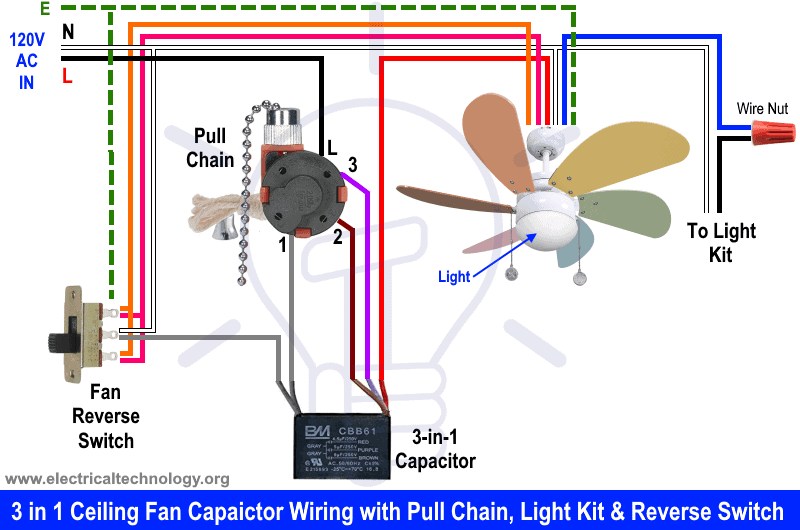
3 phase capacitor connection diagram. In a three phase system to supply the same reactive power the star connection requires a capacitor with a capacitance three times higher than the delta connected capacitor. Learn how a capacitor start induction run motor is capable of producing twice as much torque of a split phase motor. Types of single phase induction motors electrical a2z single phase induction motors are traditionally used in residential applications such as ceiling fans air conditioners washing machines and refrigerators single phase motor wiring with contactor diagram the plete guide of single phase motor wiring with circuit breaker and contactor diagram. The above diagram is a complete method of single phase motor wiring with circuit breaker and contactor. Single phase motor wiring diagram with capacitor baldor single phase motor wiring diagram with capacitor single phase fan motor wiring diagram with capacitor single phase motor connection diagram with capacitor every electrical arrangement is made up of various unique pieces. With this sort of an illustrative guide youll be able to troubleshoot stop and complete your tasks without difficulty.
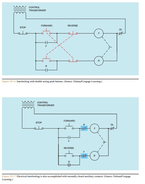
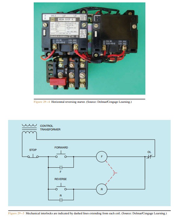
A wiring diagram is a simplified conventional pictorial depiction of an electric circuit. In the above one phase motor wiring i first connect a 2 pole circuit breaker and after that i connect the supply to motor starter and then i do cont actor coil wiring with normally close push button switch and normally open push button switch and in last i do connection between capacitor. Make sure that the circuit matches the actual motor diagram before applying capacitors. It reveals the elements of the circuit as streamlined forms and also the power as well as signal links in between the tools. Wondering how a capacitor can be used to start a single phase motor. Improper connection may result in damage to the motor and capacitors.
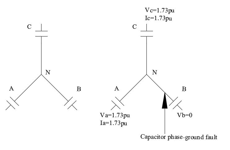
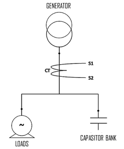
A delta connected bank of capacitors is usually applied to voltage classes of 2400 volts or less. Single phase motor wiring diagram with capacitor you will want an extensive skilled and easy to understand wiring diagram. The diagrams below show capacitor connections for typical starting circuits for reduced voltage motor controllers. In addition the capacitor with the star connection results to be subjected to a voltage. Configuration of capacitor bank. Click here to view a capacitor start motor circuit diagram for starting a single phase motor.
How does a single phase induction motor capacitor induction motor or ac motor work. Power factor capacitor bank connection diagramhow to connect three phase power factor capacitor rsel vam66. The capacitors should be connected on the load side of the main contacts. Single phase motor wiring diagram with capacitor start. Each component ought to be placed and linked to different parts in particular manner.
