Please explain to me if i must really put a contactor on my 3 phase motor. Break your circuit l n e through your contactor.

Direct Online Starter Dol Starter Working Principle Control
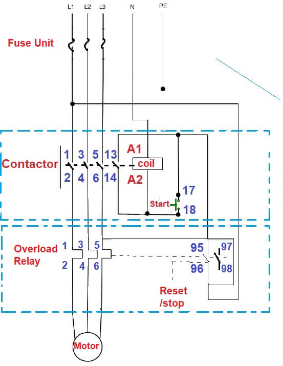
3 phase contactor connection diagram. In above contactor wiring diagram i shown 3 phase 440 volts 4 wire system. I shown the 3 pole mccb circuit breaker 2 magnetic contactor normally open normally close push button switch thermal overload relay 3 phase 4 wire system supply 3 phase motor with connection trip indicator light etc. How to wire a contactor and. A listing of electrical signs. The new diagram is best so use the new diagram connection. 3 phase motor forward reverse connection interlocking part 2.
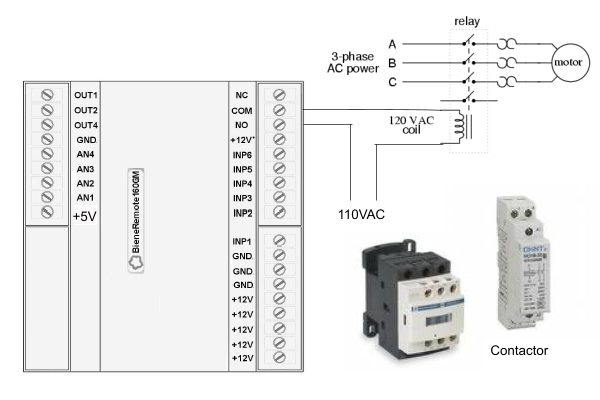
A series circuit is a circuit through which components are connected along a single path hence the. Assortment of 3 phase motor contactor wiring diagram. Contactor explained in hindi contactor wiring diagram contactor no nc working electrical dost duration. If coil required 110v to 120v then provide 110 volts supply and if it. 3 phase motor contactor wiring diagram gallery contactor wiring diagram for three phase motor. 2 contactors burned out in one day but nothing wrong with motor.
Motor is a hi low 3 phase motor on a air compressor. 240 volts ac and 480 volts ac are commonly used for these large pieces of. Many large pieces of equipment are powered directly from high voltage lines. These lines far exceed the 120 volts ac standard in most homes. The typical elements in a wiring diagram are ground power supply cable and also connection result devices buttons resistors logic gate lights and so on. In the 3 phase motor forward reverse starter wiring diagram.
I take one phase and neutral wire for mc coil which 220v but always wire your contactor coil regarding coil voltage current requirements. Using this method the current is balanced between the 3 poles on the overload. The below wiring diagram shows how we would assemble a complete motor starter with a startstop. And can i not just run it straight without a contactor. Then you connect the 2 motor leads to t1 and t3. 2 phase and 3 phase size 00 to 5 44 3 phase size 6 45 3 phase size 7 46.
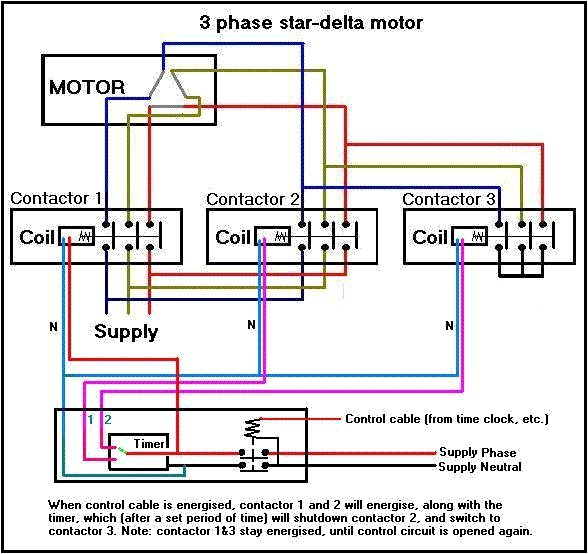
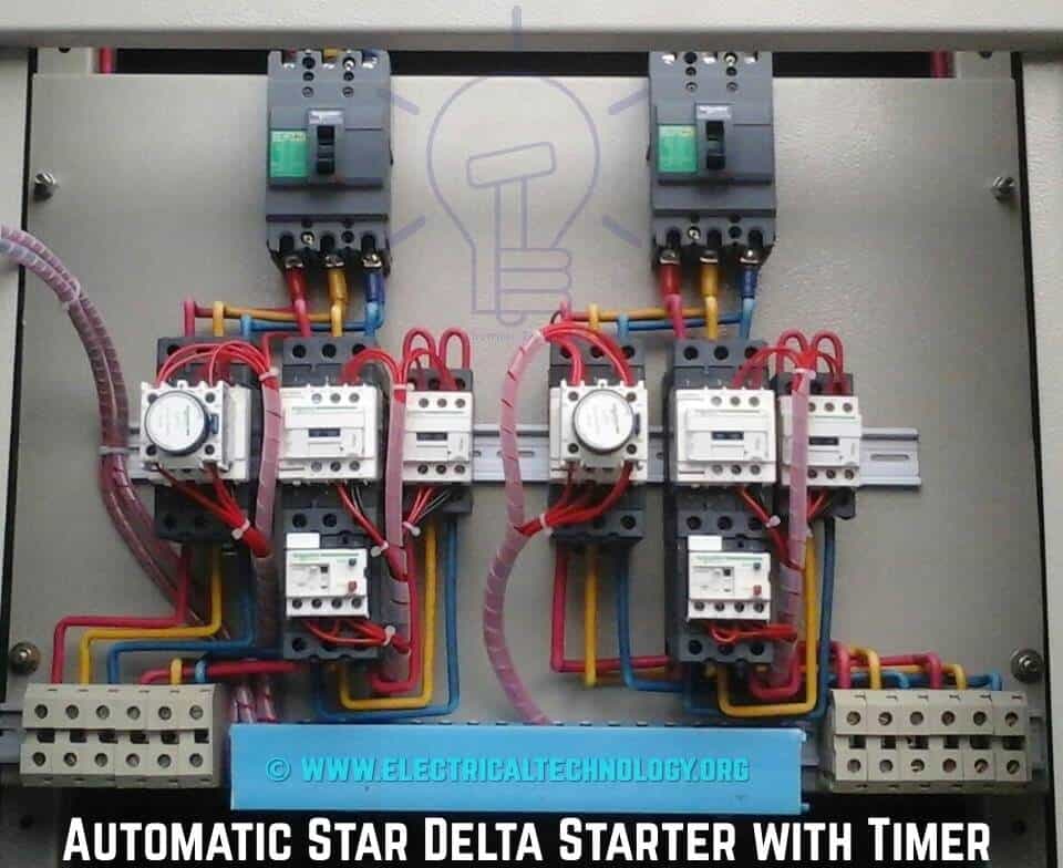
A wiring diagram is a simplified conventional pictorial representation of an electric circuit. Multispeed motor connections76 77 1 phase76 3 phase76 77 programmable. The phase voltage is lower than line voltage in star connection so the motors or drives connected in star connection runs at lower speed as compared to delta connection. How to wire a contactor. A wiring diagram is a simplified conventional pictorial representation of an electric circuit. This directs the current through from l2 and directs it through the 3 rd phase on the contactor and overload l3 t3.
You must watch this video. 2 speeds 1 direction 3 phase motor connection power diagram. Usually circuits exceeding two components have two basic types of connections.


