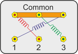
Refer to the motor manufacturers data on the motor for wiring diagrams on standard frame ex e ex d etc. Well talk about the motor and vfd and wire it up on the bench for testing before we tear into the lathe.

How To Change The Rotation Direction And Wire Configuration
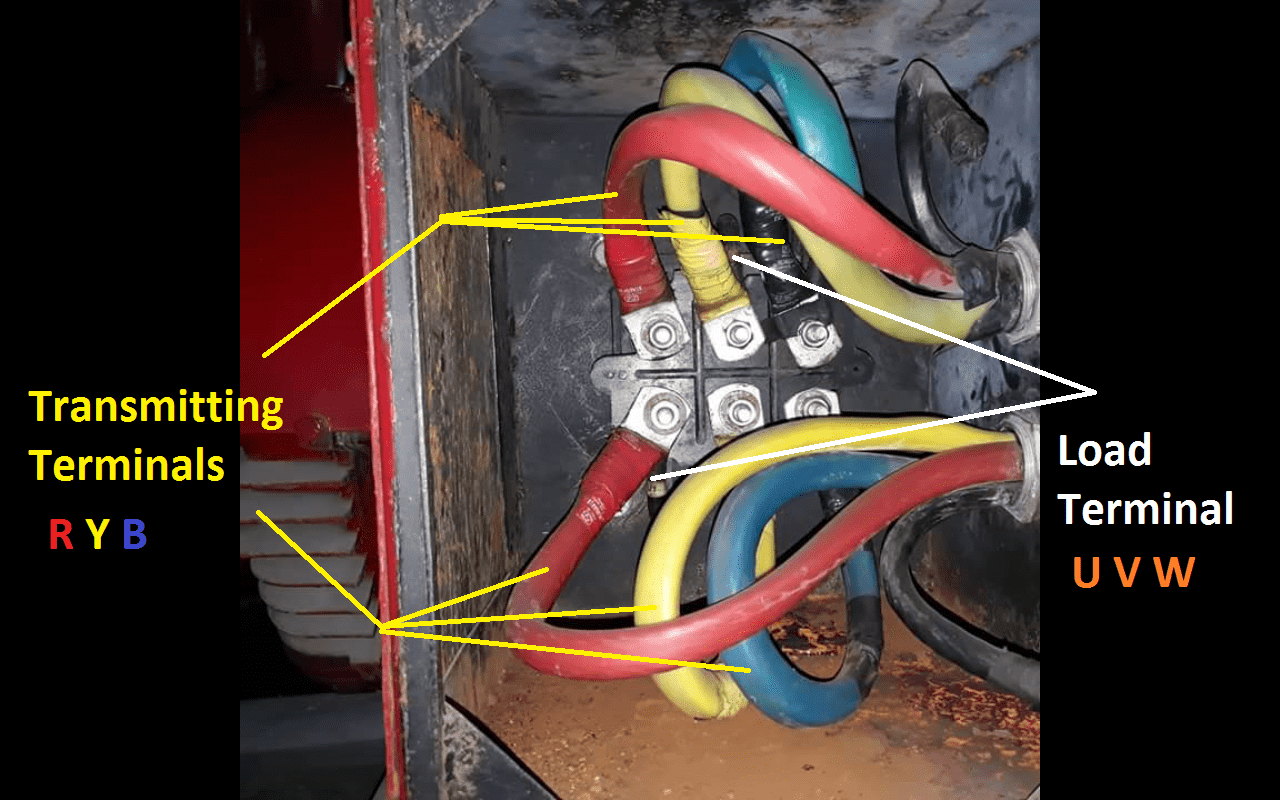
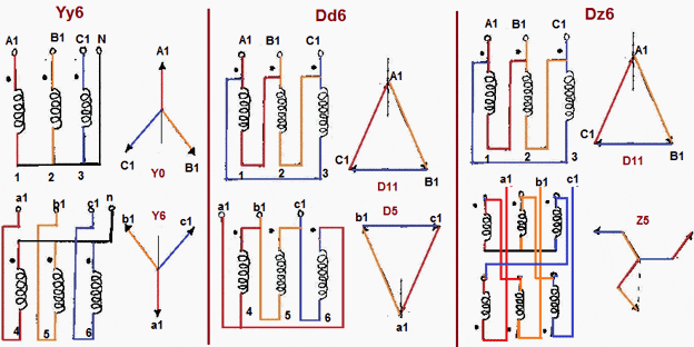
3 phase motor wiring uvw. The 3 phase motor is a rugged piece of equipment but as with everything man made there comes a time when this beautiful piece of machinery fails either due to old age misapplication mal operation or. It is a type of polyphase system and is the most common method used by electrical grids worldwide to transfer power. W2 cj2 ui vi wi w2 cj2 ui vi wi a cow voltage y high voltage z t4 til t12 10 til t4 t5 ali l2 t12 ti blu t2 wht t3org t4 yel t5 blk t6 gry t7 pnk t8 red t9 brk red tio curry tii grn t12 vlt z t4 til t12. It is one of the many labelling conventions used to denote the 3 phase wires and imply the rotation sequence. You may also come across l1 l2 l3 h1 h2 h3 a b c u v w r y b various industries have various odd conventions like uvw being. Cap it with a wire nut.
They can also be found in large residential complexes and appliances requiring a large amount of power. If there is a neutral wire in the conduit or cable supplying the motor it is unused for the motors three phase wiring. Hold the bare ends of the conductors together and twist on a wire nut. Today were starting on a 3 phase motor and vfd upgrade for the grizzly g0602 lathe. The wiring principle of most brushless dc bldc motors is similar. Generally a brushless dc motor has 8 lead wires 3 phase wires and 5 hall wires and motor controller with the corresponding.
Different regions may use different voltages. The w2u2v2 terminal set is the star side of the 3 phase motor while the u1viw1 is the delta side of the motor connected to the supply voltage. For example use a red wire nut to connect two 12 gauge wires. It is also used to power large motors and other heavy loads. Three phase systems are extremely common in industrial and commercial settings. How to wire a 3 phase motor by michael logan updated july 17.
A three wire three phase circuit is usually more economical than an equivalent two wire. Although these systems may seem intimidating at first a walkthrough on 3 phase wiring for dummies will help clarify the whole situation. These diagrams are current at the time of publication check the wiring diagram supplied with the motor. Inst maint wiring5qxd 20112015 1137 am page 6. Capacitor motor single phase wiring diagrams always use wiring diagram supplied on motor nameplate. Three phase electric power is a common method of alternating current electric power generation transmission and distribution.


