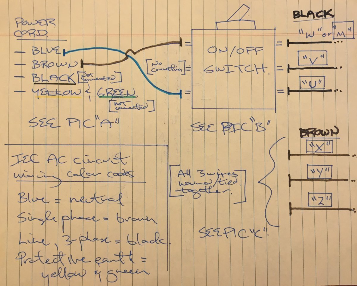
Refer to the motor manufacturers. And nc off switch and no on switch.

Gz 5763 Switch Wiring Diagrams 3 Phase Motor Starter Switch
3 phase on off switch wiring diagram. The circuit shown in figure 271 permits a motor to be operated by a float switch or to be run manually. Shown are breaker magnetic contactor thermal overload protection relay and normally open usually close push button switch. The switch is shown as a single pole. Hand off automatic controls are used to permit an operator to select between automatic or manual operation of a motor. Which is very simple to understand the complete connection. Three phase dol starter wiring diagram for 3 phase motor.
Selector switch off lo hi m 3 l1 l2 l3 n black black black red red red off lo hi m 33 l1 l2 l3 n suggested wiring arrangement selector switch hi speed contactor overload overload lo speed contactor these diagrams are current at the time of publication check the wiring diagram supplied with the motor. Automatic ups inverter wiring connection diagram to the home. Single phase dol starter wiring diagram animation duration. The answer to how it works is to have an extra hot wire that runs between the two switch boxes. The most important rationale is that there are several ways that a three way switch can be wired. Start stop of 3 phase induction motor with the help of magnetic starter on off three phase motor connection power control schematic wiring diagrams.
Single phase motor wiring is too simple connection but every person can not do it easily. Today this post is specially for complete method of single phase motor wiring with switch off on circuit breaker. How to make a remote on and off switch with a contactor latching circuit duration. In other words a 3 way switch is made up of one light thats controlled by two separate switches. This will be the complete guide to controlling a three stage submersible pump motor using magnetic contactors. In the above one phase motor wiring i first connect a 2 pole circuit breaker and after that i connect the supply to motor starter and then i do cont actor coil wiring with normally close push button switch and normally open push button switch and in last i do connection between capacitor.
3 phase submersible pump motor and electric wiring connection. My creative engineering 3187 views. Hand off automatic controls recognize hand off automatic switches on a schematic diagram. For single phase motor we can use one way switch 1 pole circuit breaker and 2 pole circuit breaker for controlling off on. In the diagram you will see the three pole mccb circuit breaker molded case circuit breaker a magnetic contactor a motor over current thermal overload protection relay. Wiring a 3 way switch isnt that difficult.
Time lapse of schematic diagram drawn into a wire diagram and the wiring of the magnetic motor starter. In the diagram i found the 3 pole mccb. The above diagram is a complete method of single phase motor wiring with circuit breaker and contactor.


