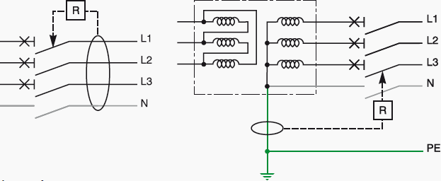
You can directly connect the 3 phase on 3 poles of rccb without neutral. The figure below shows schematic diagram for industrial three phase wiring.

How To Wire An Rcd With No Neutral Line Control Logic Blog
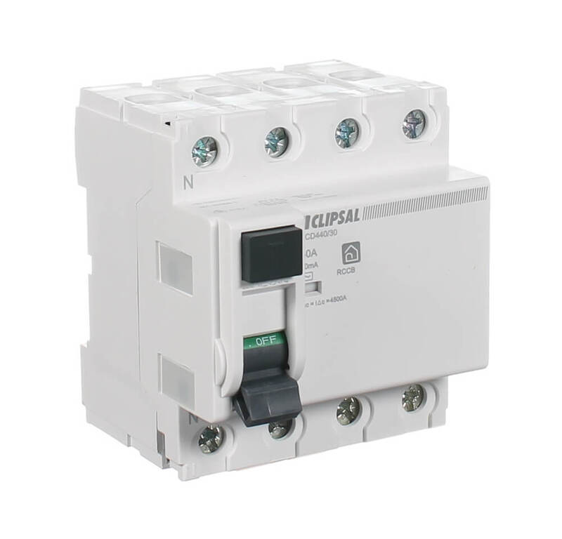
3 phase rcd wiring diagram. For wiring rcd four pole circuit breaker connect your incoming 3 phase 4 wire supply to the input connection of fixed rcd eg example connect neutral n and phases l1 l2 l3 to input terminals and then get supply form out terminals as shown in below diagram. Electricalonline4u a platform to learn electrical wiring single phase 3 phase wiring controlling hvac electrical installation electrical diagrams. Dual rcd consumer unit duration. Please refer the attached sheet for connection resistance values to e used with multi9 range of rccb. A complete diagram of single phase distribution board with double pole mcb wiring rcd wiring volt meter wiring and light indicator. Single phase meter wiring diagram energy meter energy meter connection by earthbondhon.
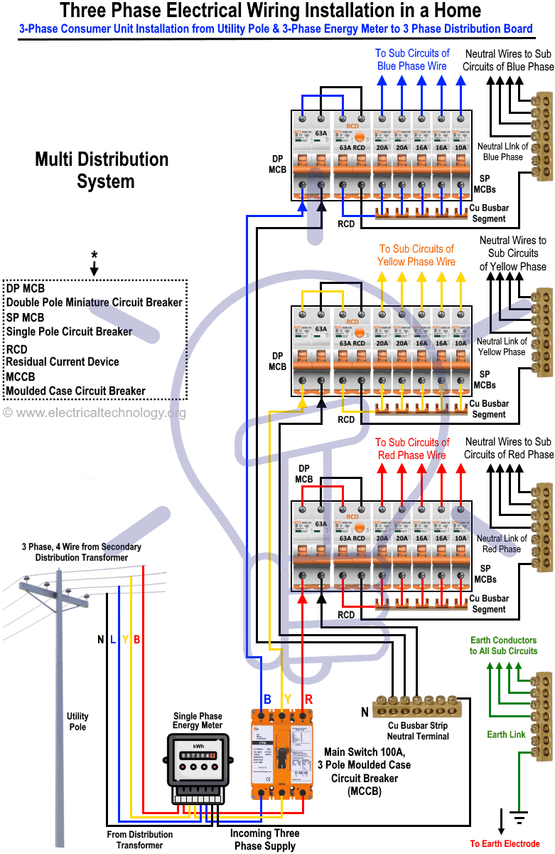
Three phase energy meter. If you are using the multi9 id range rccb we need to add a resistance with specific resistance values to be compliant with 380 415v. In this single phase home supply wiring diagram the main supply single phase live red wire and neutral black wire comes from the secondary of the transformer 3 phase 4 wire star system to the single phase energy meter note that single phase supply is 230v ac and 120v ac in usthese two lines line and neutral from energy meter are. In our today electrical wiring installation tutorial we will show how to do a three phase consumer unit installation from utility pole to a 3 phase energy meter 3 phase distribution board and then how to connect single phase three phase loads in a three phase wiring distribution system in home electric supply system. In the above figure power from the utility pole is connected to sub circuits via three phase energy meter three phase breaker 3 pole 60a double pole rcd double pole mcb and single pole mcbs. John ward 393526 views.
Demand of these three circuits must not exceed rating of rcd ol n n n a neutral link do not earth ol clipsal rcd 2 4n 1 3n a mains switch a e n n an. Clipsal rc and 4rc series residual current device wiring diagrams 1 2 main switch single phase e 3n 4n clipsal rcbm 4rcbm and 4rcbe series combined mcbrcd wiring diagram a warning combined max. How to wire rcd residual current device.

