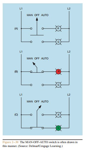
Single phase motor wiring diagram with capacitor sources. In this video i guide complete about ammeter rotary switch and its.
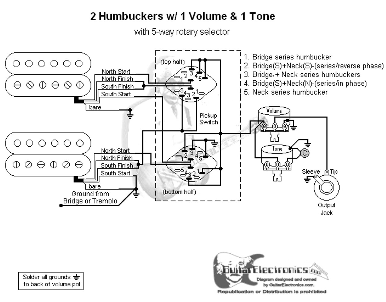
2 Humbuckers 5 Way Rotary Switch 1 Volume 1 Tone 03
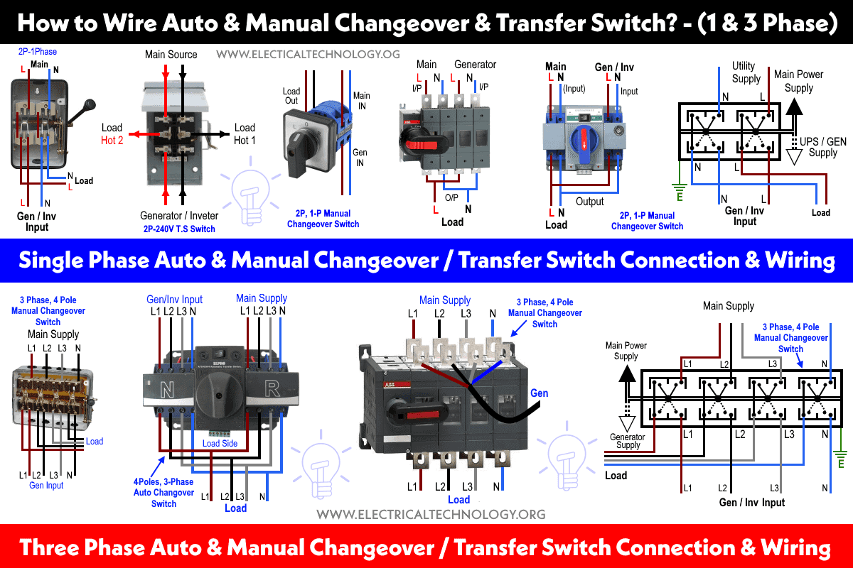
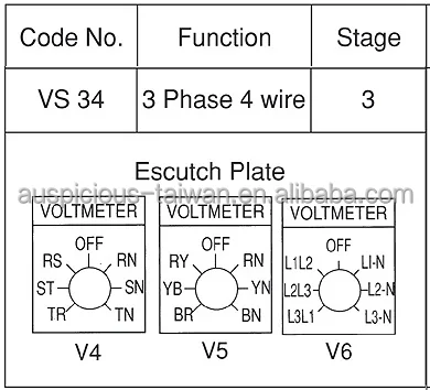
3 phase rotary switch connection diagram. In this post i also write about voltmeter selector switch connection wiring but in the last time i talk and publish diagram about the 3 phase and in this post you will learn how to measure 3 phase 4 wire system voltage using a voltmeter selector switch. 2 speeds 1 direction 3 phase motor connection power diagram. Hello friend in this video i will explain u how to do wiring and switching of 3 phase change over from 3 phase electric meter to 3 phase generator mode for more information comment down in the. 1 cm and 5mm thick mdf board 2. The left side four slots connection points are connected to the load then. The three phase utility power as l 1 l 2 l 3 n are directly connected to the upper side of manual changeover switch while the backup power of three phase generator is connected to the first four right slots of at lower side.
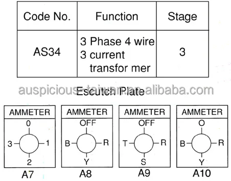
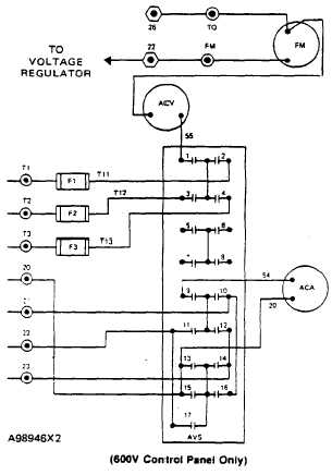
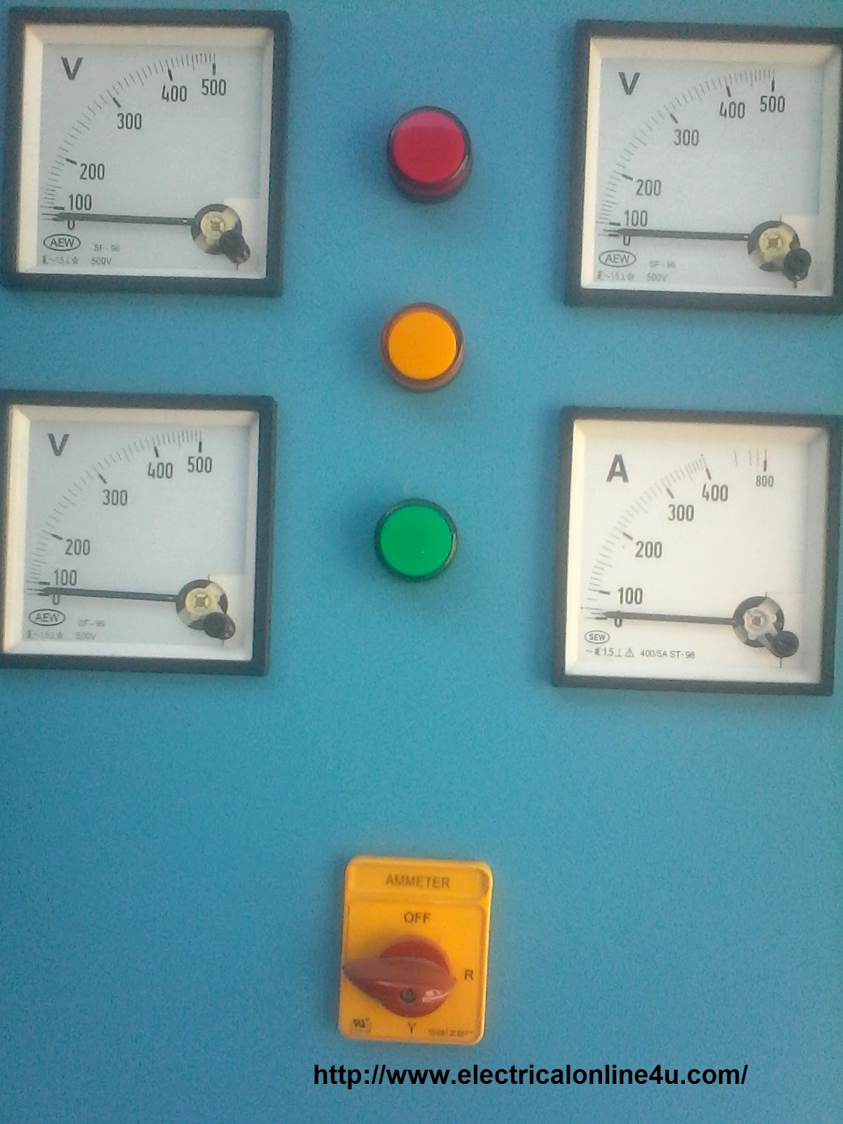
Single phase motor wiring diagram forward reverse collections of phase meter wiring diagram single phase motor capacitor wiring. The electricity enters the rotary switchs input terminal and the switch sends electricity to the output terminal selected. A toggle switch for switching on off the voltmeter 1 5. A complete guide of ammeter selector switch wiring diagram or rotary switch wiring diagram for 3 phase system load testing. Voltmeter selector switch wiring which was about the three phase voltage measuring and in which we did not talk about the neutral connection. Following materials were used.
The poles are the three legs in the centre and the ways are the legs around the outside. These contain two or more input terminals called poles. The ways are grouped together in sets of four legs and each set corresponds to one pole hence the name 3 pole 4 way. Some rotary switches contain more than one circuit. 720 copper wire a few meters 7. Three phase 3 line connection consist of three phase conductors and is employed only where there is no requirement for connecting phase to neutral loads.
Three phase systems can be three phase three wire or three phase four wire systems. 63 amp rated 3 terminal connectors 2 4. Off push switch stop should be nc reply. 2a is a 3 pole 4 way switch. This is shown by the text 34 in the centre. The rotary switch pictured in fig.
0 230 v digital voltmeter 1 5. These connections can be star or delta depending on the secondary of the distribution transformer. Phase indicator lamps ryb 3 6. A rotary switch connects several devices to an electric source. 63 amp 4 pole changeover switch on load type 3 its lt make model number was not mentioned anywhere 3. Hi can i please get a simple control and power diagram for a 2speed.
Witch overload should be greater high speed or low speed. Wiring diagram for single phase motor fresh pretty single phase. With single phase motor with capacitor forward and reverse wiring.
Gallery of 3 Phase Rotary Switch Connection Diagram

