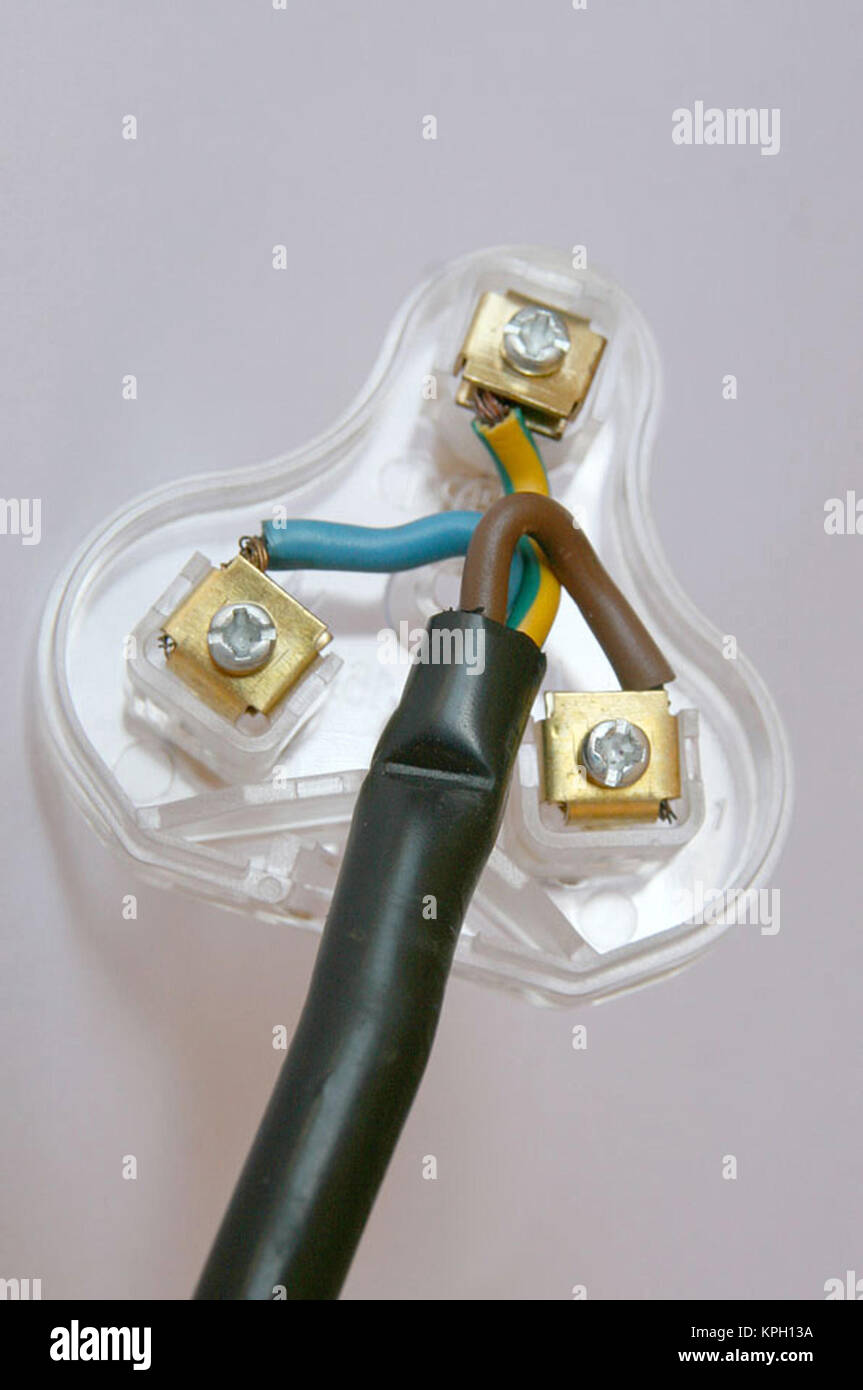
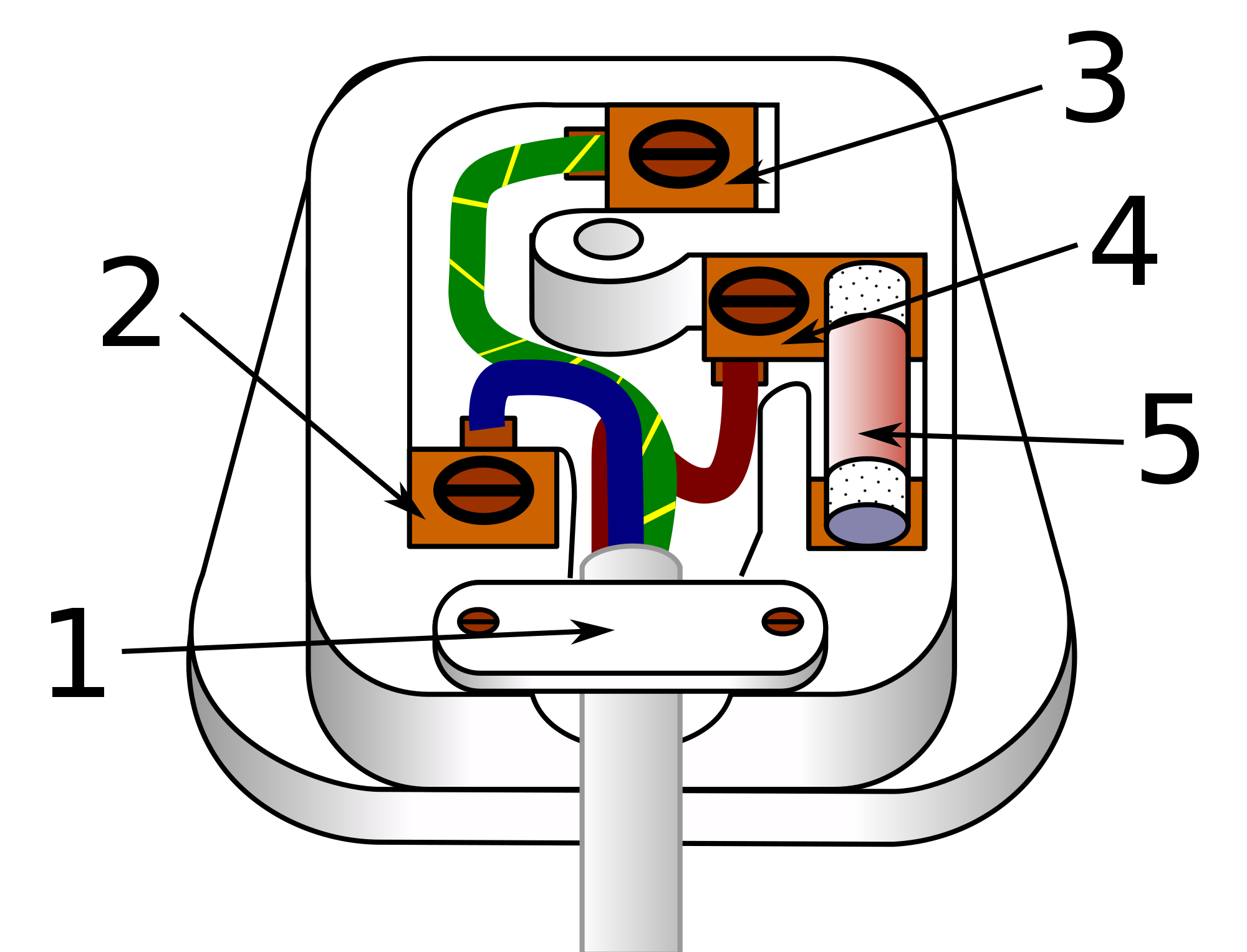
Unscrew the little screws on each of the plugs pins. Insert the twisted copper wires into the holes in the pins.

Title Mains Electricity 2 Objectives To Know Ppt Video
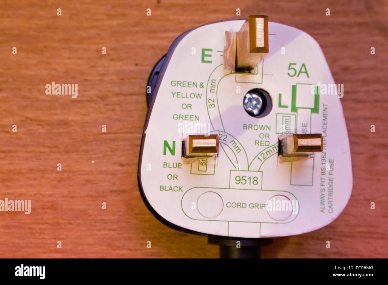
3 pin plug wiring diagram. The blue wire is inserted into the left pin the pin is marked with a blue spot or the letter n. Swing the gate open and place the wire in the holder. Image trees and power lines. The rear view is the end you solder from here are the connections on each pin. Collection of 3 pin led flasher relay wiring diagram. Unsubscribe from asd electrical electronics projects.
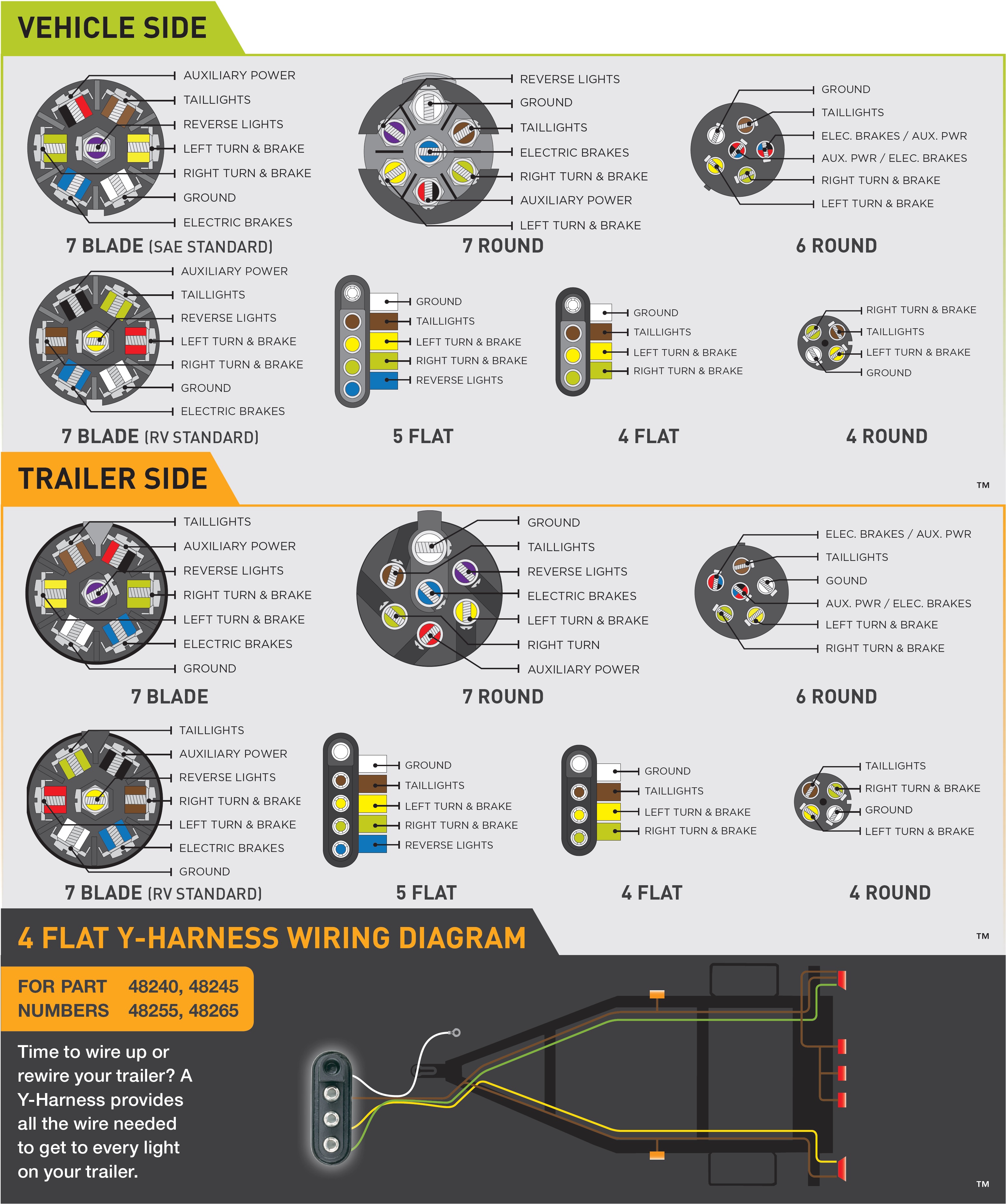
In the trailer wiring diagram and connector application chart below use the first 5 pins and ignore the rest. Image child playing with electrical outlet. Wiring diagram parts list design worksheet duration. How to wire a plug. 3 pin xlr wiring standard. The green and yellow wire must always be inserted into the top pin.
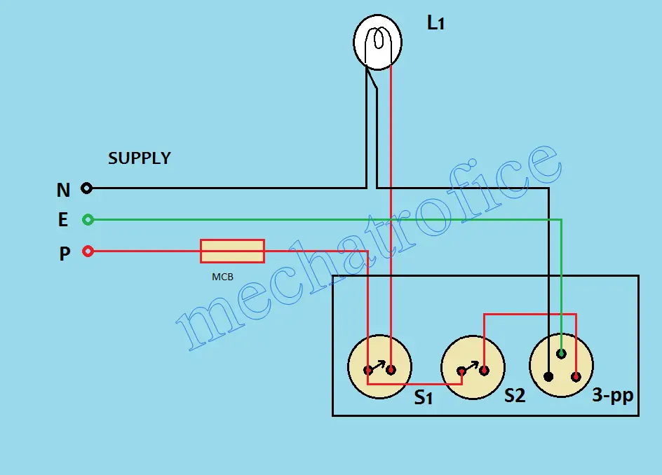
A ul knot secures the cord. 3 pin xlr connectors are standard amongst line level and mic level audio applications. A wiring diagram is a simplified conventional photographic depiction of an electric circuit. 3 pin plug wiring diagram three pin plug diagram three prong plug wiring diagram asd electrical electronics projects. Unscrew one screw from the main cable holder and remove the screw completely. Make sure the wire is held in place around the outer sheath.
If your truck has a built in 7 pin socket but you only need 5 of the pins. 5 pin industrial socket wiring demonstration plug chfrsia. A wide variety of 3 pin plug wiring diagram connector options are available to you such as power automobile and home appliance. Image typical three pin plug. It reveals the elements of the circuit as streamlined forms and the power and also signal links between the devices. Use the 7 pin connector anyway see below and just leave out the last 2 wires.
If youre wiring a 3 prong plug you need 2 conductor cable with a ground. How to wiring the cable of 5p industrial sockets and plugs. The above diagram shows you the pin numbering for both male and female xlr connectors from the front and the rear view. Close the gate again and secure the screw back into place. Image maintaining clearance around power lines. Most plugs use a small plastic gate secured by screws to hold the cable in place.
Remove the plug cover by either snapping or unscrewing it. The hot wire goes on the brass terminal screw the white wire goes on the chrome one and the ground wire goes on the green one. In 110v plug wiring youre dealing with 14 or 12 gauge wire.
