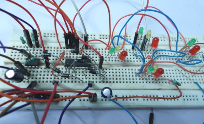
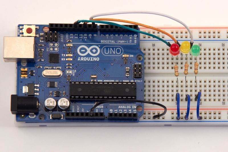
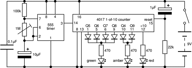
The red led has an equal on off period and when it is off the first 555 delivers power to the second 555. Circuit diagram and code for this arduino traffic light.

Ht 4706 Traffic Light Controller Circuit Diagram Free Diagram
3 way traffic light circuit diagram. The timer here generates pulses of time period 100ms approximately. Click image to enlarge. Circuit diagram of traffic light control mini project. So the on time is 50ms and off time is 50ms. 3 leds green red and yellow. Here is a kind of infographics showing the circuit diagram for any level of user with other information.
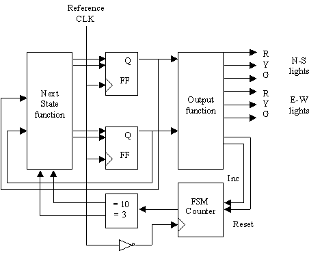
Traffic lights circuit heres a clever circuit using two 555s to produce a set of traffic lights for a model layout. Here have demonstrated it for 3 sides or ways. We have covered a more simpler version of traffic lights in this traffic light circuit. In the oscillator ic1 is connected as the astable multivibrator circuit to generate the frequencies. So at the start the green light of signal 1 and red. The schematic diagram of the traffic light circuit in update version.
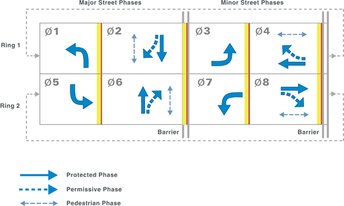
The animation shows the lighting sequence and this follows the australian standard. Although street lights have a shift time for 2minutes here we are reducing. We have covered a more simpler version of traffic lights in this traffic light circuit. This traffic light controller will be used to control the flow of traffic. Traffic signal lights are very important to regulate vehicles and traffic on roads simple four way traffic light circuit is designed with timer ic 555 and counter ic cd4017. The tunnel circuit control the lamps in four ways as follow.
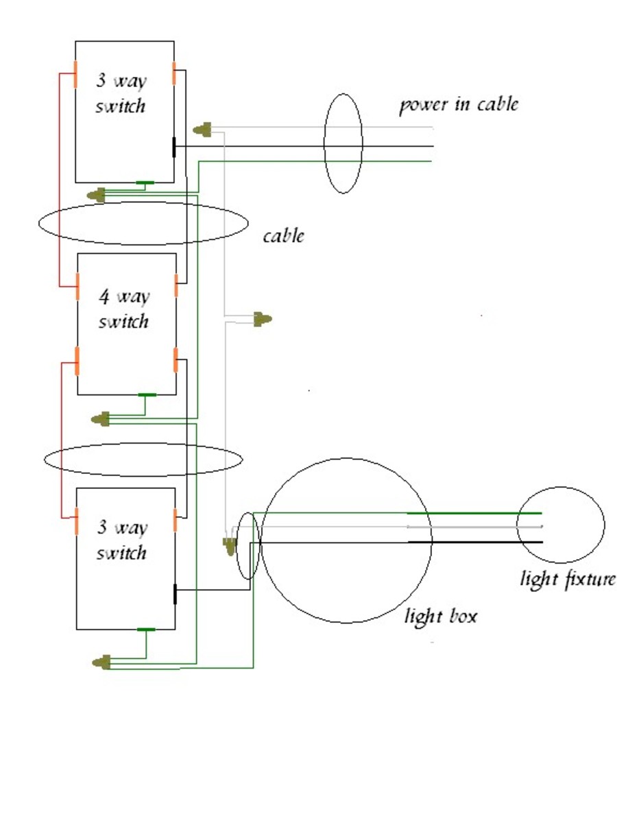
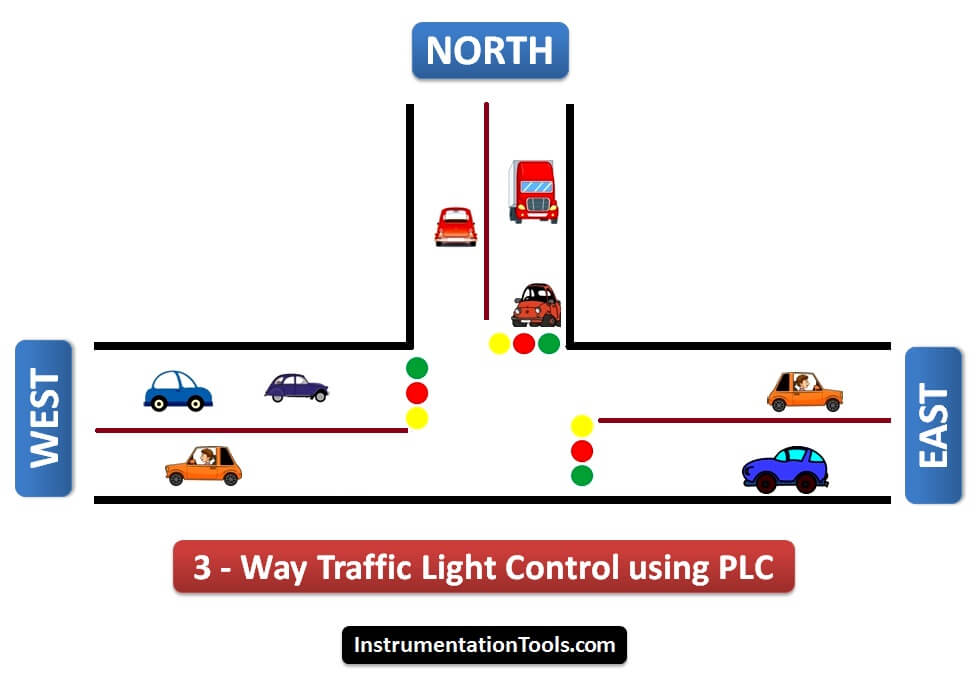
Here have demonstrated it for 3 sides or ways. This is not the real time traffic light controller. In tunnel wring circuit diagram we have used spdt two way switches to control the lighting points in tunnels and corridors. We know each traffic signal light setup will have three colors and representing red for stop yellow for wait and green for go those signals are works based on time intervals. Tm1637 seven segment led display. This frequency is determined by r1r2vr1c1.
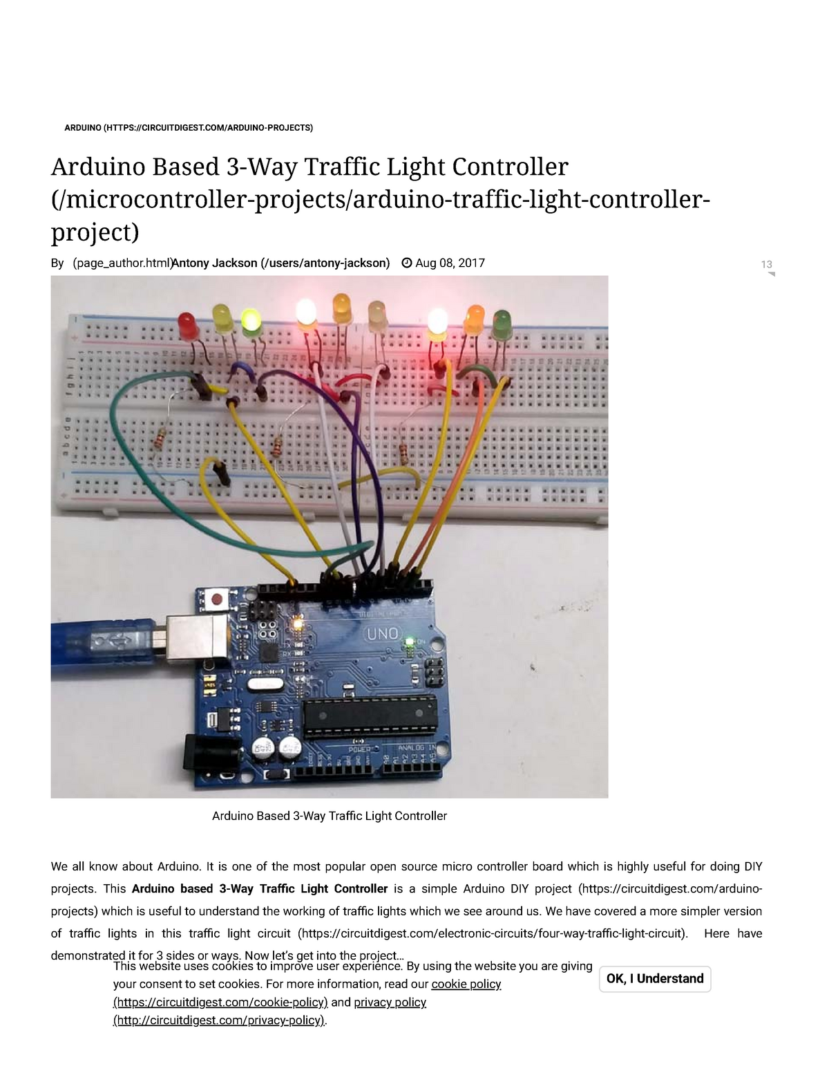
This project is done to give you an idea of how the traffic light controller works. Now lets get into the project. This arduino based 3 way traffic light controller is a simple arduino diy project which is useful to understand the working of traffic lights which we see around us. This time duration can be changed by changing the capacitor value. Now lets get into the project. From 7am to 6pm only the middle one bulb will glow and the first and last one will turned off.
Traffic light has proved to be an amazing way to stop the vehicular collisions and control the traffic jams in todays modern era where everyone owns the different types of vehicles. This arduino based 3 way traffic light controller is a simple arduino diy project which is useful to understand the working of traffic lights which we see around us. These can be applied at high traffic areas to avoid traffic blocks or accidents. Then this output frequency will appear at pin 3 of ic1 into pin 14 of ic2. Four way traffic light circuit diagram using 555 timer ic is shown in the above diagram. During normal light in the day ie.
