In this diagram the incoming hot wire attaches to the first switchs common dark colored terminal. Gx 3 way valve and actuator july 2017 5 figure 4.

3 Way Valve Wiring Diagram Wiring Diagrams
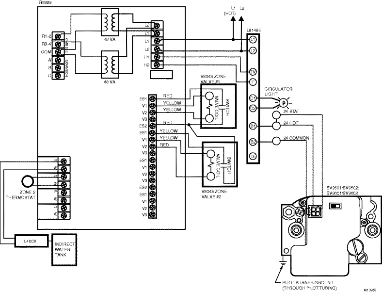
3 way valve wiring diagram. The two hot wires of three wire cable connect to a pair of brass colored traveler terminals on each switch. Take a closer look at a 3 way switch wiring diagram. Speak to you later raden kevin. Electrical installation pertaining to honeywell 3 port valve wiring diagram image size 800 x 718 px and to view image details please click the image. This might seem intimidating but it does not have to be. With these diagrams below it will take the guess work out of wiring.
This has one inlet and two outlets one for hot water the. This 3 way switch wiring diagram shows how to wire the switches and the light when the power is coming to the light switch. Honeywell 3 way valve wiring diagram wiring diagram is a simplified enjoyable pictorial representation of an electrical circuitit shows the components of the circuit as simplified shapes and the capability and signal friends in the company of the devices. These 2 way 3 way and 4 way solenoid valves can handle most fluid control applications and are now available with class i division 2 approvals we also offer a complete line of general service isolation pinch proportional valves and manifold assemblies for use in medical equipment analytical instrumentation and industrial applications. 3 way switch wiring diagram. Body nut key 7 torque.
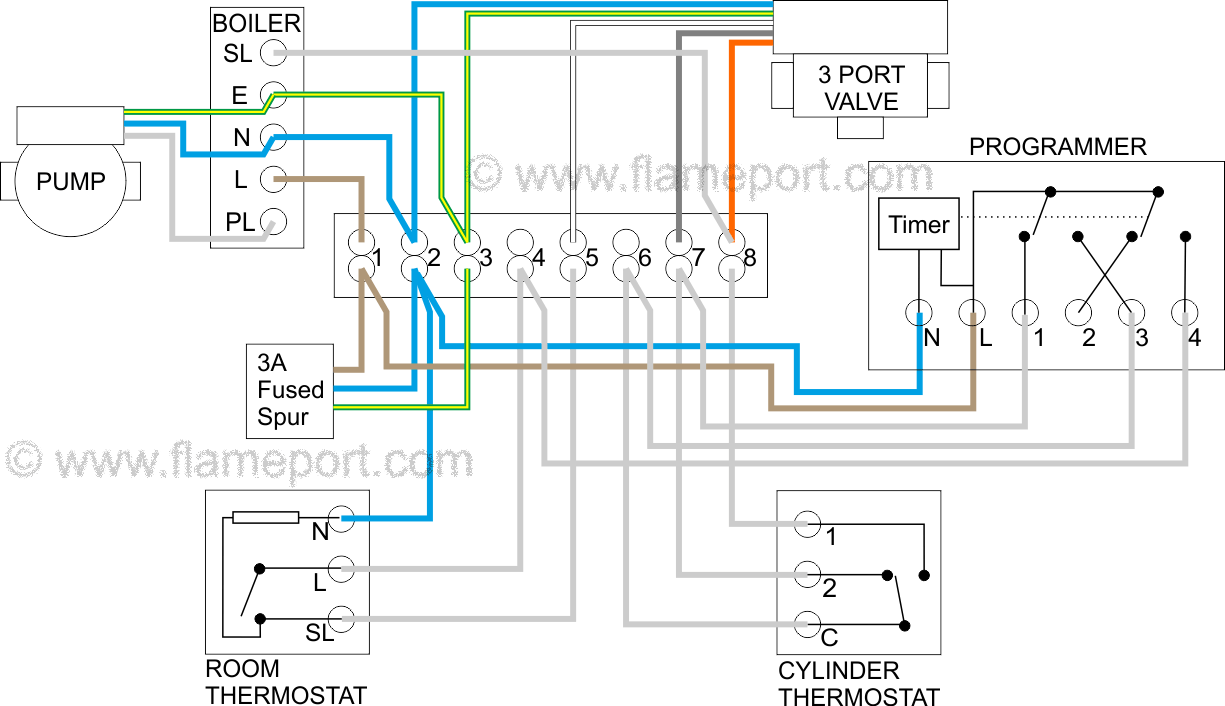
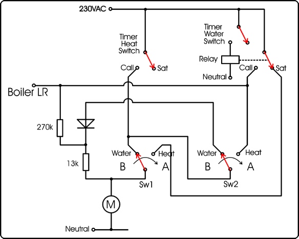
Pick the diagram that is most like the scenario you are in and see if you can wire your switch. Fisher gx 3way valve sideport common flow direction ge37477flowdir table 2. A cct diagram will certainly do the job so if anybody has one to hand it would be most appreciated. Part 4 in the heating wiring series covers how the 3 port mid position valve works internally allowing 3 separate positions from only 2 mains inputs. Fisher gx 3way rated travel valve size actuator size number of casing bolts travel stem connector gap settings nps mm 1 112 225 6 19 21 2 750 10 19 21 3 4 750 10 38 40 table 3. Here is a picture gallery about honeywell 3 port valve wiring diagram complete with the description of the image please find the image you need.
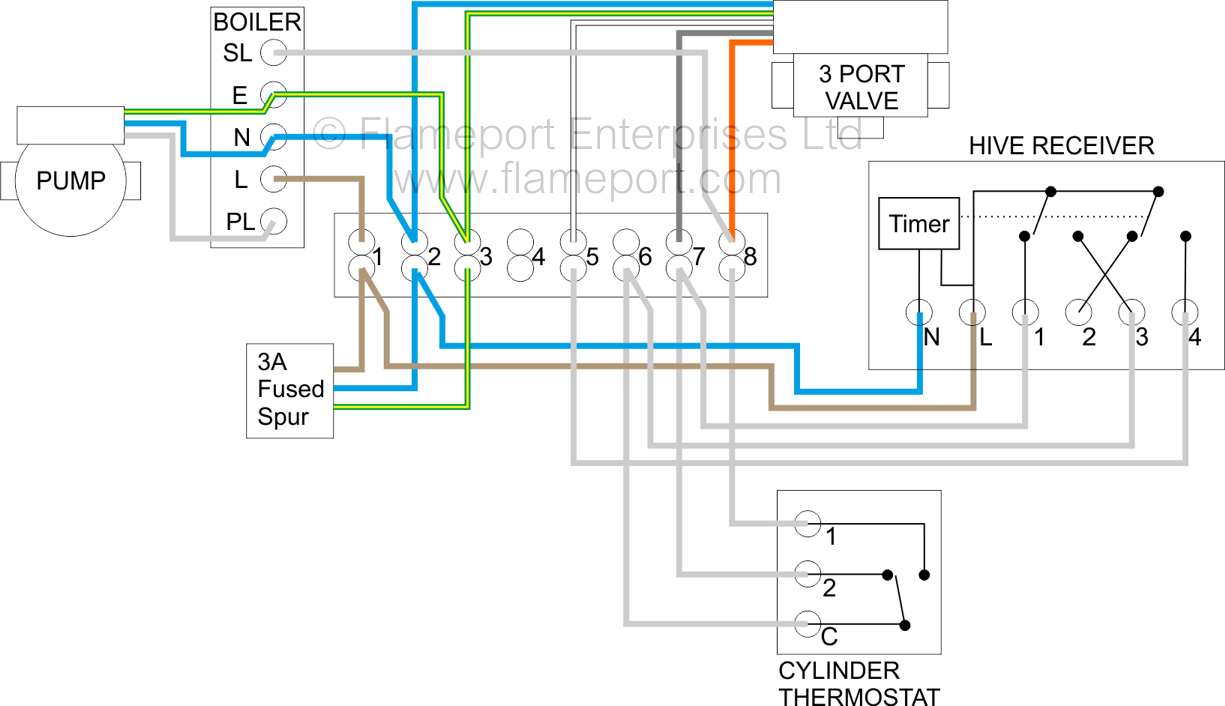
I might even be able to locate a wiring diagram. Part 3 in the series looks at y plan wiring a system which uses a single 3 port valve. Includes a clock 3 way valve stats and a wiring centre. Electrical wiring for central heating systems.


