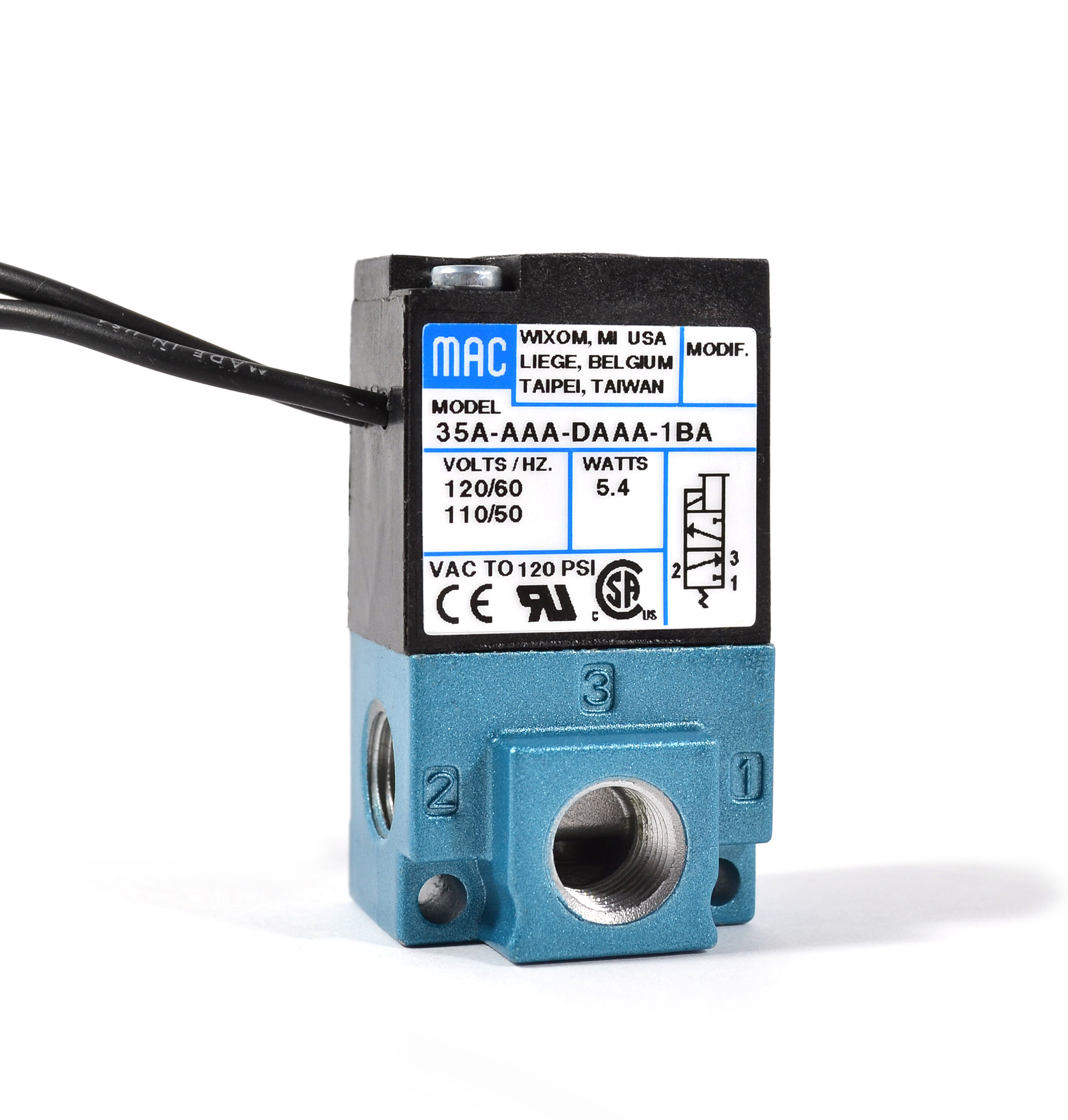
Mac valves solenoid operated 4 way. It has a detented spool to allow for adjusting linkage without shutting off air pressure.

5 3 Way Air Pilot Valve Inlet Outlet 3 8 Npt Exhaust 1 4 4a330c 10 Npt
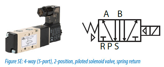
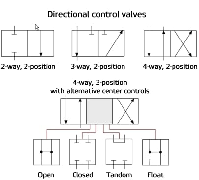
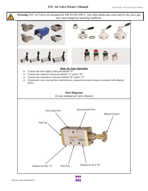
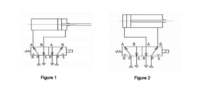
4 way air valve diagram. 14 manual air control valves with 3 way 3 position air valve type feature fluorocarbon seals and a stainless steel spool for greater chemical compatibility and the ability to withstand higher temperatures. They create two actions and have two exhaust ports which allows you to control the speed of each action by attaching a flow control valve to each exhaust port. Small 4 way valves. Usually contain 4 or 5 ports air in from compressor usually marked p air out a to one side of cylinder air out b to other side of cylinder exhaust out ea exhaust out eb only on 5 ported valves. 4 way solenoid valves required to operate double acting cylinders. 4 way reversing valves construction a 4 way reversing valve has four ports for tube connections.
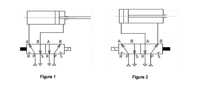
Air flows up to 12 cv. The following diagram shows a 4 way solenoid valve connected to the piston actuator of a larger process ball valve. This type of valve is used to completely reverse the flow in a reversible system. The center position blocks air at valve while opening both cylinder ports to atmosphere. Large 4 way valves. In the off position these valves exhaust all air pressure allowing the equipment to return to the neutral position.
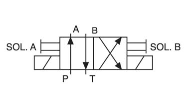
Inlet a common exhaust and two cylinder ports one normally open and the other normally closed. This is a holdover from hydraulics where the two exhaust paths are joined internally to the valve so that only one return port is required and only one return line is required to get the hydraulic oil back to the storage tank. The same diagram could be drawn using the triangle solenoid valve symbols rather than the block symbols more common to fluid power diagrams. Also known as 4 way and 53 exhaust center valves. Air flows from 12 cv and hihger. Such valves may be used when both heating and cooling modes are required or to provide an effective energy efficient defrosting method.
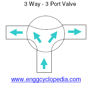
This video describes working principles of a five port four way valve. 4 and 5 ported valves flow diagrams de energized press. Numatics 4 way 2 position manual air control valves. Their common application is to operate double acting cylinders. Buyers products 4 way 3 position air valve controls the air flow required for precise operation in many air cylinder applications. Valves with 4 ports.
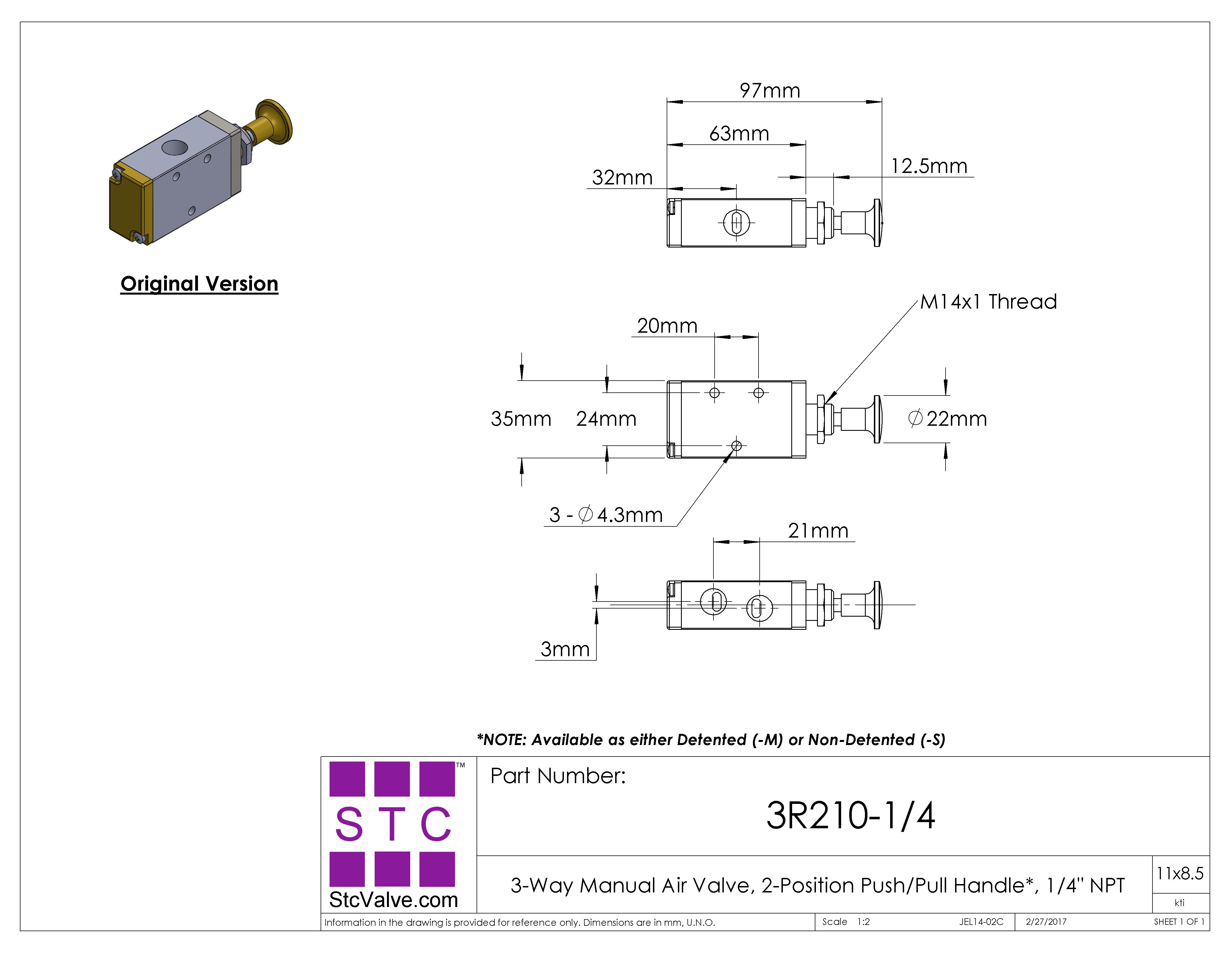
It has five ports but it is considered a 4 way valve because two of the ports share the same exhaust function. Series general description pipe size npt page 8340 air only 14 83 8342 general service 14 and 38 87 8344 pistonpoppet 14 1 89 8345 general service 14 93 84018402 slide valve 14 95 85518553 inline spool valve 14. This valves spool shift from natural position with air pressure and return to natural position by spring.
Gallery of 4 Way Air Valve Diagram