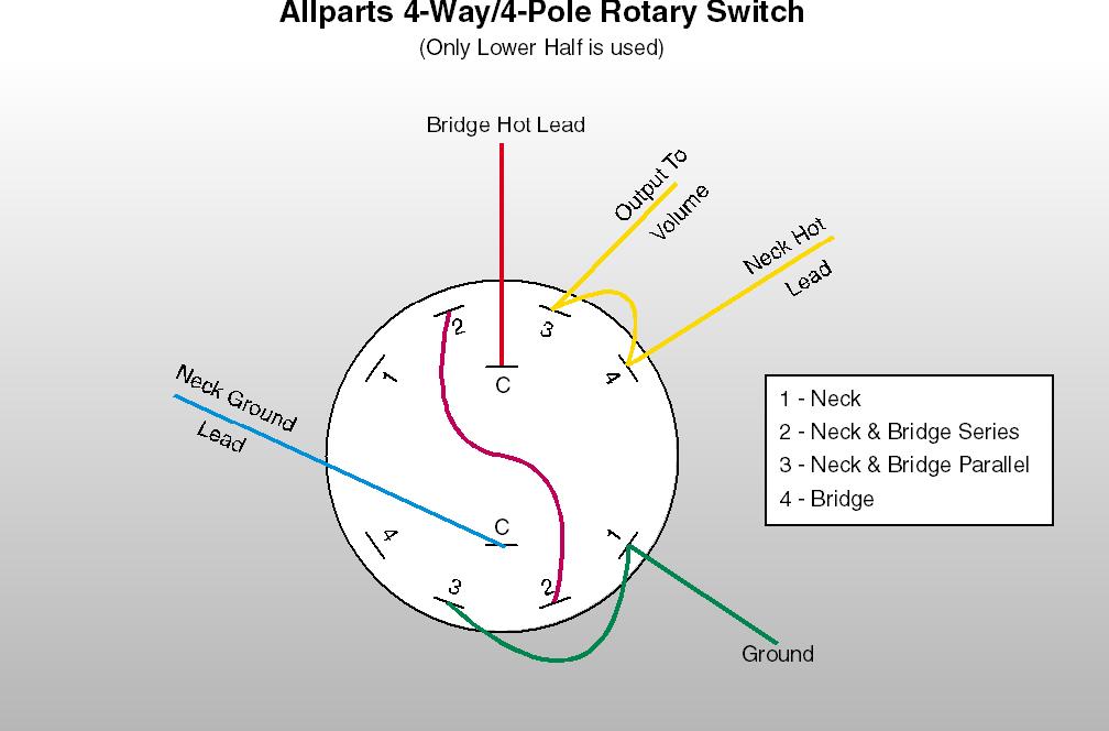
Assortment of fender telecaster 3 way switch wiring diagram. In response to the requests for this information i have developed a comprehensivestep by step guide designed to walk you through the identification and wiring of your 3 way switches.
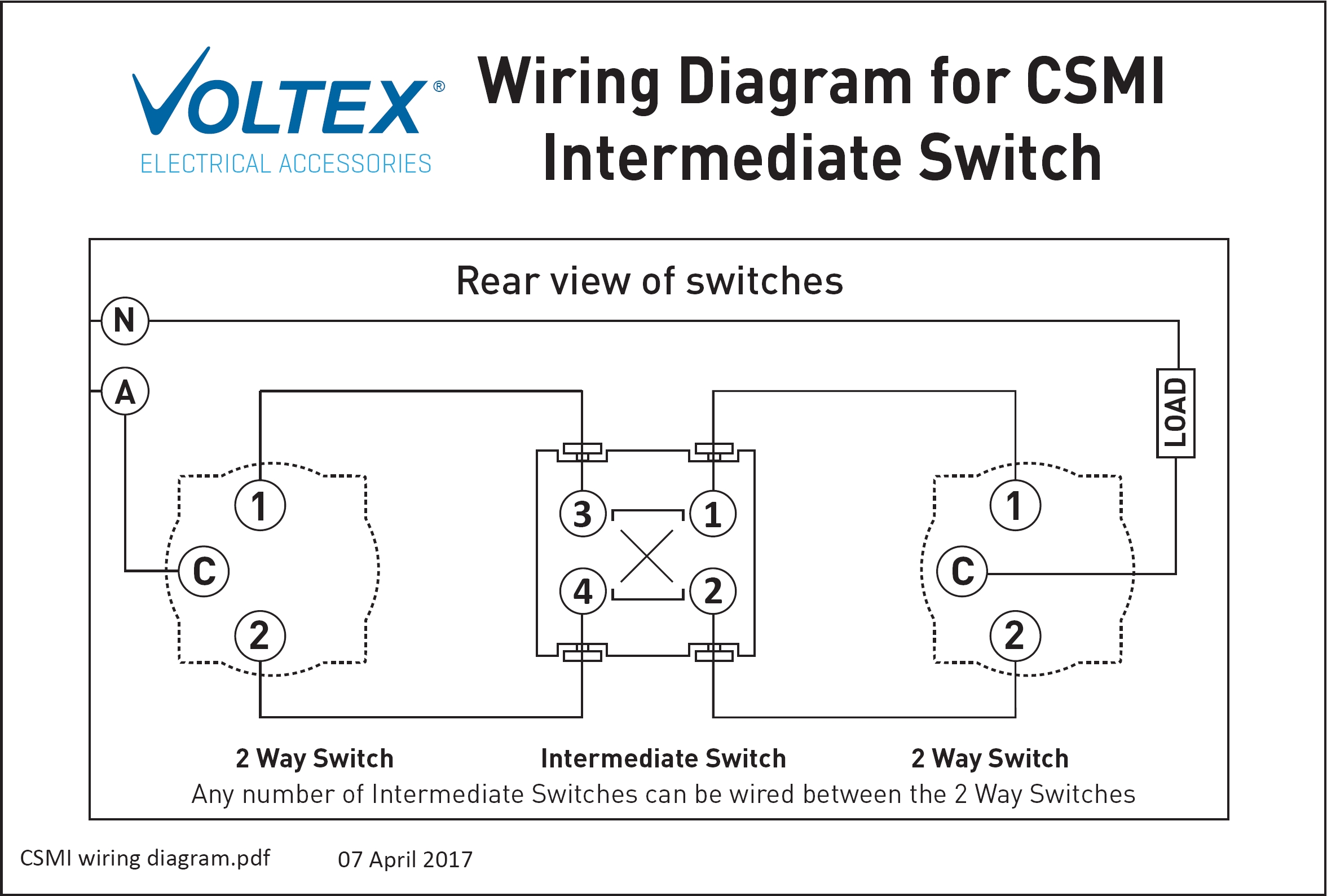
Diagram Based 3 Way Lighting Diagram Completed Diagram
4 way switch wiring diagram pdf. The diagrams below show the conventional wiring for 3 way switches in a 4 way configuration. 3 way switch wiring diagram helpful for wiring 4 way switches which are wired with 3 way switches. Below is a conventional wiring diagram for a 4 way switch configuration. 4 way dimmer switch wiring diagram. A typical four way switch wiring diagram. Electrical 4 way switch wiring diagram.
Electrical wiring diagram 3 way switch. A wiring diagram is a simplified standard pictorial representation of an electrical circuit. This might seem intimidating but it does not have to be. Notice in this diagram you can see the actual operation of the switches. It shows the parts of the circuit as simplified forms and also the power and signal links in between the tools. 21 posts related to hunter 4 wire ceiling fan switch wiring diagram.
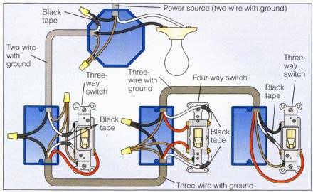
See alternate 3 way switch wiring configuration for another way 3 way switches may be wired. Three wire cable runs between all the switches and 2 wire cable runs to the light. The white wire of the cable going to the switch is attached to the black line in the fixture box using a wirenut. To make this circuit work a 3 way dimmer can be used in place of one or both of the standard 3 way switches. This is the wiring for a dimmer in a 4 way circuit. Assortment of 3 way switch wiring diagram pdf.
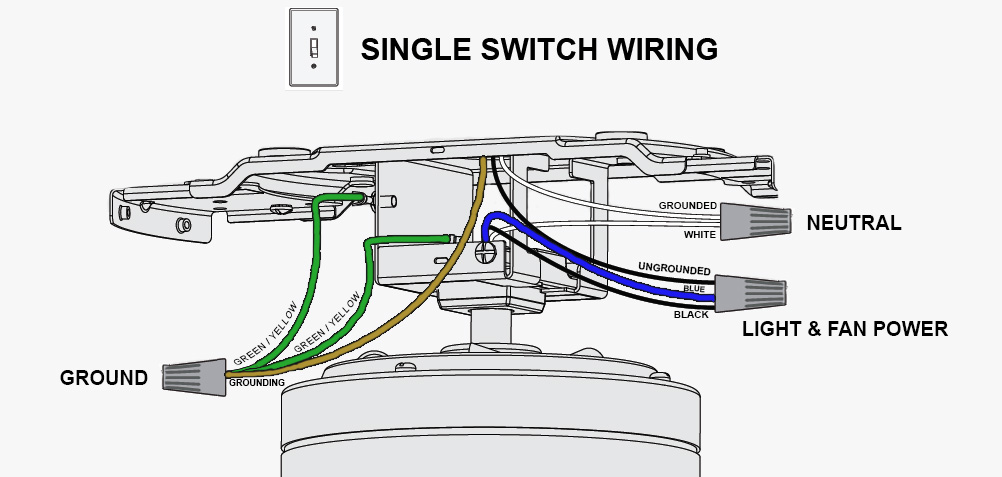
Unfortunately not all 3 way switches are wired the conventional way. A wiring diagram is a simplified conventional photographic depiction of an electric circuit. This 4 way switch diagram 2 shows the power source starting at the fixture. Subject verb agreement quiz pdf. It shows the elements of the circuit as streamlined shapes and the power and also signal links in between the devices. Hunter ceiling fan wiring diagram switch.
Pick the diagram that is most like the scenario you are in and see if you can wire your switch. In the wiring diagram above we can see the 4 way switch installed between the two 3 way switches. With these diagrams below it will take the guess work out of wiring. 4 way switch wiring diagrams this 4 way switch diagram 1 shows the power source starting at the left 3 way switch. The white wire becomes the energized. The solid line is the actual switch position while the dotted lines show the alternate position.
You can put multiple 4 way switches in between two 3 ways. Subject verb agreement ks2 worksheet tes. The load wire is in one 3 way switch box and the line from the power source is in the other 3 way switch box. 4 way switch schematics can also be used for intermediate switches. Four way switch wiring diagrams. The 4 ways are in between.
Take a closer look at a 3 way switch wiring diagram.
