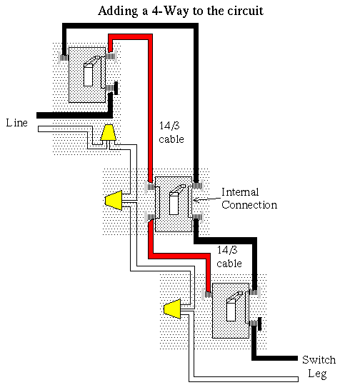
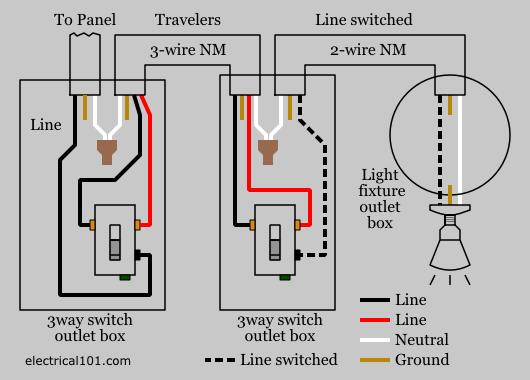
Three wire cable runs between all the switches and 2 wire cable runs to the light. A 3 wire nm connects the traveler terminals of the first 3 way switch and the first 4 way switch.
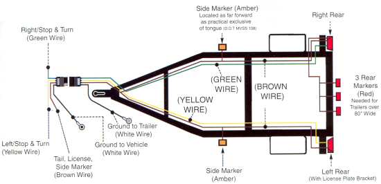
Trailer Wiring Diagram For 4 Way 5 Way 6 Way And 7 Way Circuits
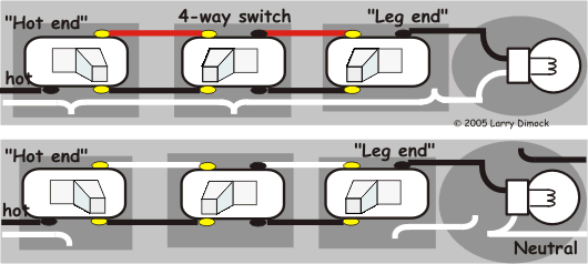
4 way wiring diagram. 4 way switch wiring 4 way switches provide switching from three or more locations. One way to check for faulty wires is to use a circuit tester. No matter how i wire going from neck pos. For complete instructions on wiring a basic 4 way switch see our wiring a 4 way switch article. If additional 4 way switches are needed they will also go between the 3 way switches. They all must be between the two 3 way switches.
Four way switch wiring instructions inside the switch packaging. 4 way dimmer switch wiring diagram. Typical 4 way switch wiring nm cable. This is the wiring for a dimmer in a 4 way circuit. In the 1st diagram below a 2 wire nm cable supplies power from the panel to the first switch box. 4 way switch wring diagram.
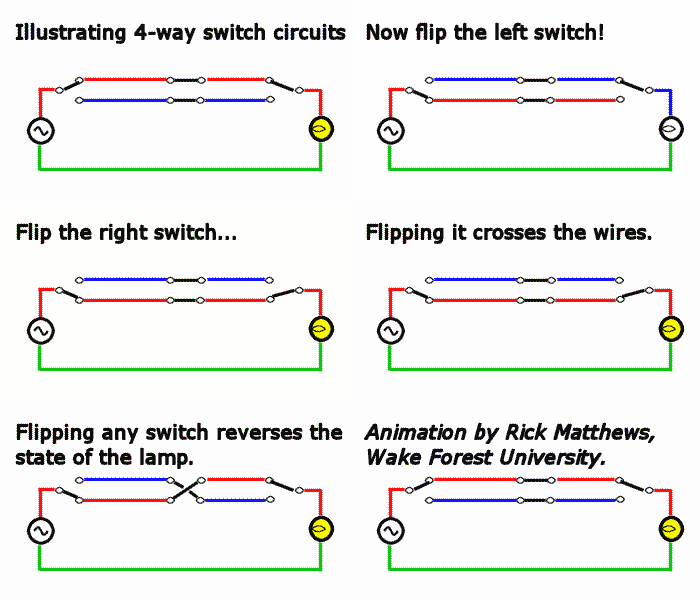
Make sure that all cables are electrically conductive. If more than three switches are needed simply place more 4 way switches between the three way switches. A 4 way switch is always placed in between two 3 way switches. To view it at full size click on the diagram. The wiring connections on 4 way switches varies between manufacturers. To make this circuit work a 3 way dimmer can be used in place of one or both of the standard 3 way switches.
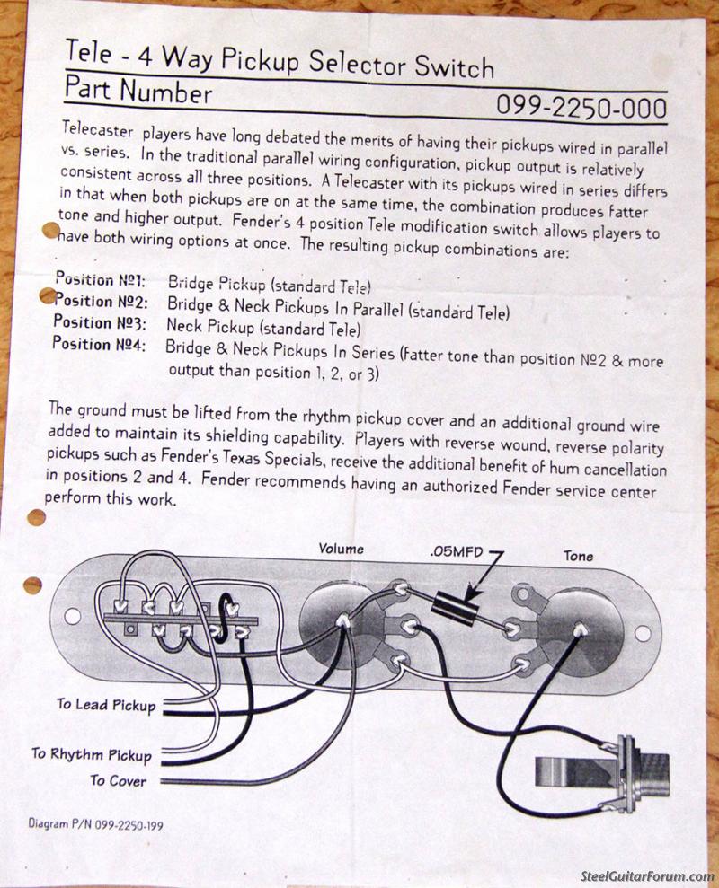
As you will see most 4 way switch wiring is placed between the wiring of two 3 way switches therefore a 4way switch is installed with two 3way. If you understand how to wire a 3 way switch youll have no issues with a 4 way switch. If it is not no amount of wiring will get the lights to work. 4 to the series combo pos. Click here to access note. 3 it cuts out dead.
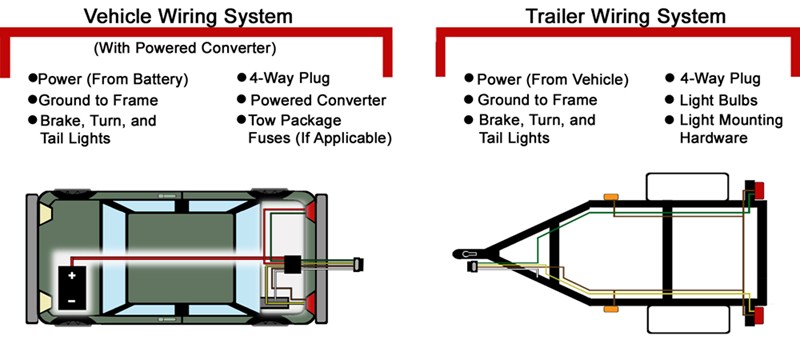
Installing your 4 pin trailer wiring system is easy if you follow the correct procedure. Everything works except this. Trailer wiring diagrams 4 way systems. 4 way flat molded connectors allow basic hookup for three lighting functions. Right turn signal stop light green left turn signal stop light yellow taillight license side marker brown and a ground white. You can have an indefinite number of 4 way switches in a circuit.
The black line wire connects to the common terminal of the first 3 way switch. Sometimes there is only a switch wiring diagram printed on the inside of the 4 way switch package box. Thanks tyler for your clear wiring diagrams for a 4 way. The first thing you need to do is make sure that your connector works properly. Watch the 4 way switch video below and pay attention. The 4 way is used when you want to control the light or lights from two or more locations.
The two wiring diagrams above are of a 3 way switch setup and the same basic setup with a 4 way light switch added. This diagram is a thumbnail. Its the 3rd or 4th try with a peavey generation series 2 tele copy but i have a persistent problem. With 4 way switches you must read the manufacturers instructions or wiring diagram. While the physical location of the 4 way switch may be anywhere the electrical location of the switch is always between the two 3 way switches.


