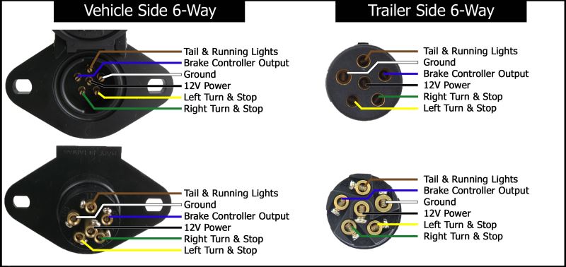
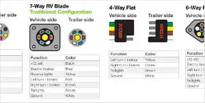
7 way trailer connectors are used by the following vehicle types. Trailer wiring diagrams trailer wiring connectors various connectors are available from four to seven pins that allow for the transfer of power for the lighting as well as auxiliary functions such as an electric trailer brake controller backup lights or a 12v power supply for a winch or interior trailer lights.

Trailer Wiring Diagrams North Texas Trailers Fort Worth
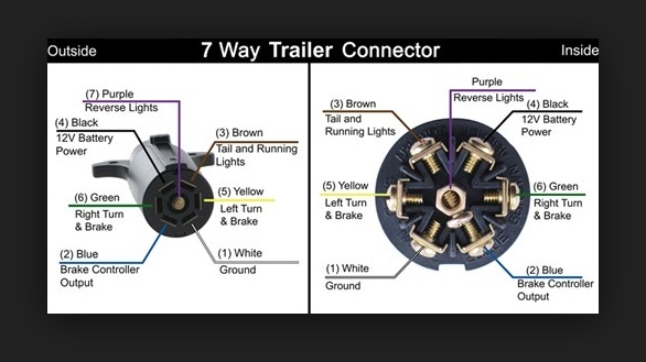
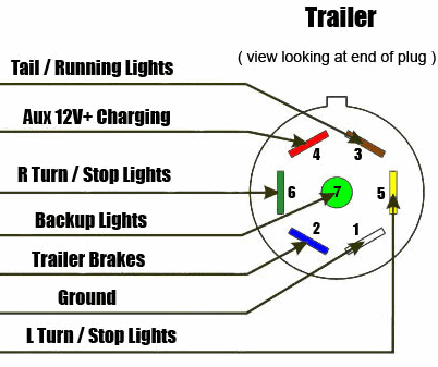
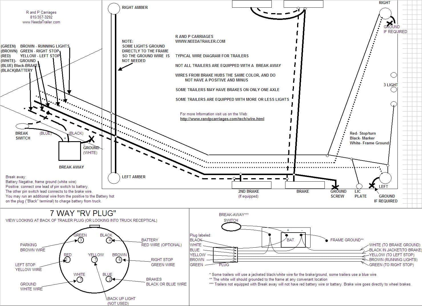
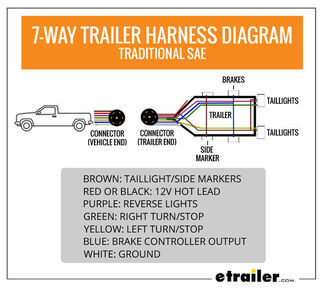
7 way boat trailer wiring diagram. If not the arrangement will not function as it ought to be. Tm park light green battery feed black rt right turnbrake light brown lt left turnbrake light red s trailer electric brakes blue gd ground white a accessory yellow this is the most common standard wiring scheme for rv plugs and the one used by major auto manufacturers today. On most recreational vehicles. 7 way trailer wiring diagram is explained in details in the picture and the table below. 7 way plug wiring diagram standard wiring post purpose wire color. By law trailer lighting must be connected into the tow vehicles wiring system to provide trailer running lights turn signals and brake lights.
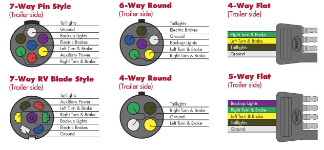
Check with a test light or vom. Round 2 diameter connector allows additional pin for auxiliary 12 volt power or backup lights. Large 5th wheel trailers. Trailer electrical connectors come in a variety of shapes and sizes. Each component ought to be set and connected with different parts in particular manner. The basic purpose remains the same whether your truck and trailer is using a 4 way 5 way 6 way or 7 way connector.
7 pin trailer wiring diagram with brakes 7 pin flat trailer wiring diagram with brakes 7 pin rv trailer wiring diagram with brakes 7 pin trailer wiring diagram with brakes every electrical arrangement is made up of various different parts. Heavy duty landscaping trailer car trailer boat trailers horse trailer travel trailer construction trailer etc. 7 pin trailer wiring diagram with brakes.
