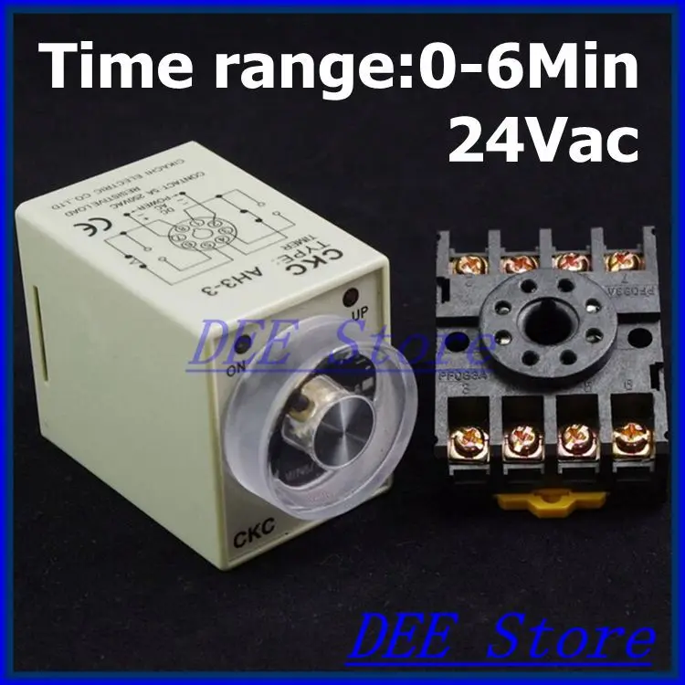
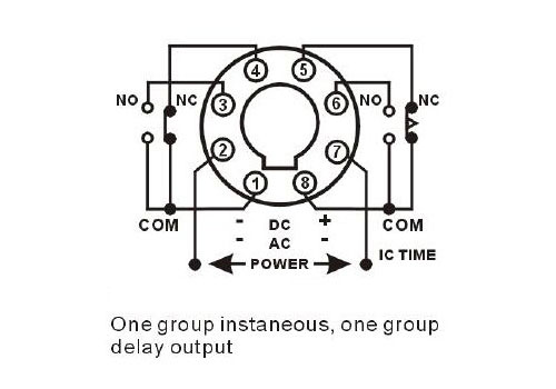
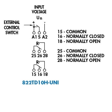
Relay 8 pin wiring diagram datasheet cross reference circuit and application notes in pdf format. Ato time delay relay also available with 8 pin mounting socket for din rail.

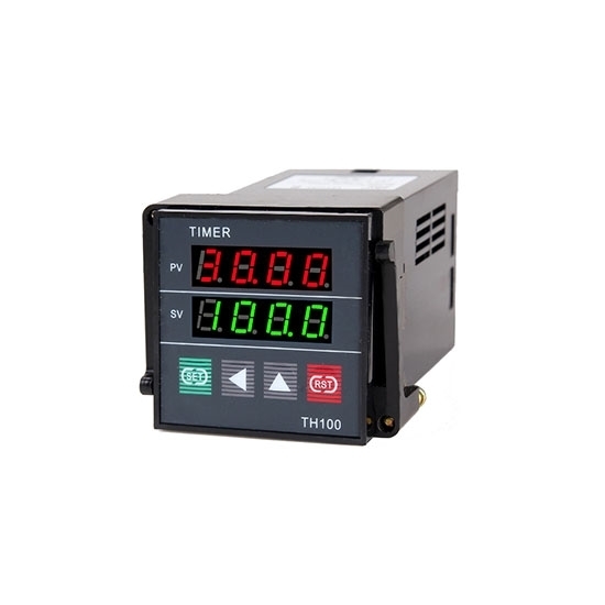
Hd Digital Timer 8 Pin Timer Relay View Digital Timer Toky Product Details From Toky Electrical Co Ltd On Alibaba Com
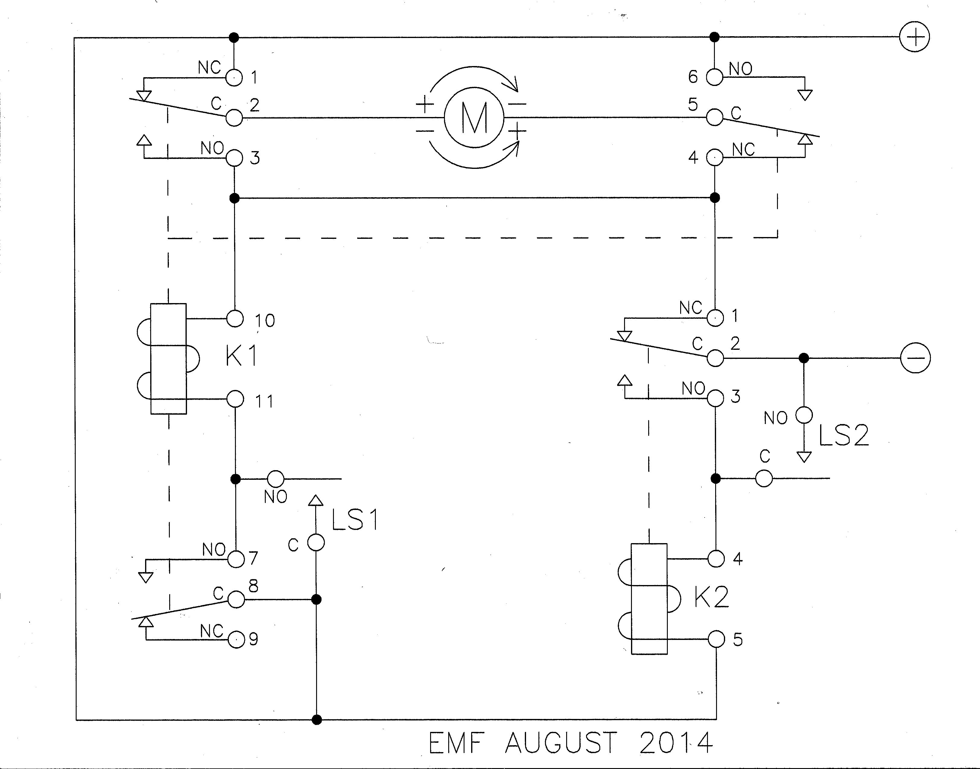
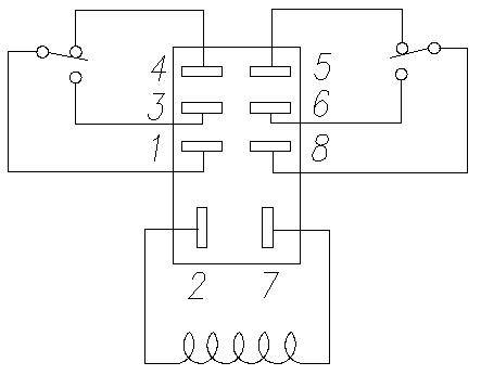
8 pin time delay relay wiring diagram. Start stop wiring basics duration. 12 240v acdc coil range. These relay are connected in a socket which is also called base. By looking at the diagram below we can go through the basic concept of a relay and how they operate. 8 pin relay wiring. 8 pin relay wiring diagram.
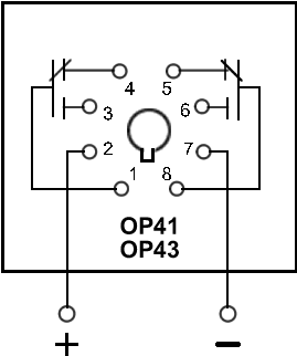
This post is about the 8 pin timer wiring diagram. A run down of how an 8 pin relay base is to be wired and the contacts stand for. Pins 8 6 as normally open pins 8 5 as normally closed. Pins 8 6 as normally open pins 8 5 as normally closed. Dayton time delay relay wiring diagram dayton time delay relay wiring diagram wire rh kmestc 8 pin schematic 8 pin relay. 10 timing functions included.
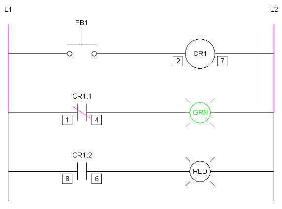
Ladder and wiring diagram using an 8 pin electrical relay to turn on and off lights. On delay power triggered single shot leading edge voltage controlled off delaysignal off delay single shot leading edge with control input flasher pause first retriggerable single shot flasher on first onoff delay. With this kind of an illustrative manual youll have the ability to troubleshoot stop and full your assignments without difficulty. This diagram will show you how simple it is to control motors lights valves other relays and any type. 4pdt wiring diagram trusted wiring diagrams. Note that to wire a 8 pin timer we use the 8 pin relay socket.
Ladder diagram basics 1 duration. See my switch terminology page for more on contact arrangements if you need to. Daytons time delay relay features an interval on function with an adjustable timing range of 01 10 seconds 120v acdc input voltage and 10a dpdt output contacts utilizing an 8 pin octal socket. New cube relay wiring diagram. Mostly we use the 8 pin timer in ats system automatic transfer switch star delta starter and many other places where we needed the timing in circuit. If you want to start the device after a.
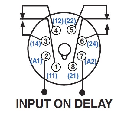
Potter brumfield relay wiring diagram collections of potter brumfield relay wiring diagram collection. 8 pin ice cube relay wiring diagram sample. 8 pin relay wiring diagram you will want an extensive expert and easy to comprehend wiring diagram. 8 pin timing relay 240v rated 10 amp spdt. The time relay is divided into the on delay timer and the off delay timer. The below diagram is on delay timer wiring diagram.
