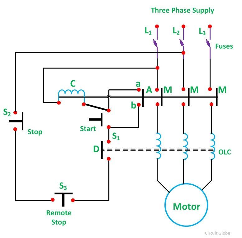
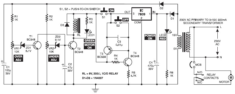
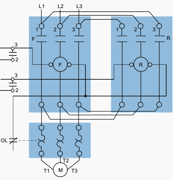
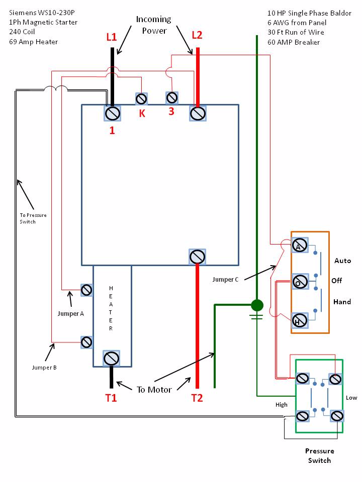
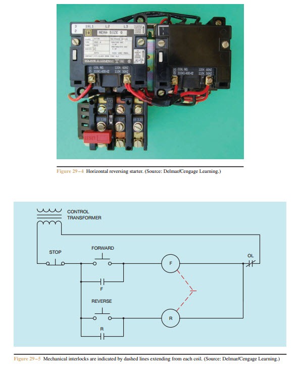
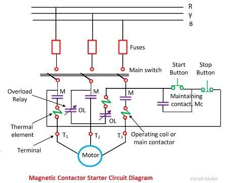
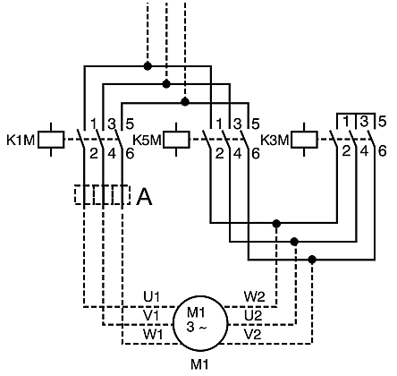
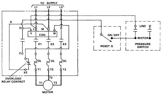
Wiring diagrams sometimes called main or construction diagrams show the actual connection points for the wires to the components and terminals of the controller. A motor starter is a combination of devices used to start run and stop an ac induction motor based on commands from an operator or a controller.
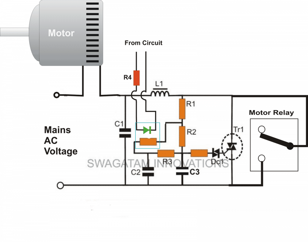
Adding A Soft Start To Water Pump Motors Reducing Relay
Ac motor starter wiring diagram. Large electric motors with a high starting torque like an air conditioners compressor motor often use a start capacitor kit. In north america an induction motor will typically operate at 230v or 460v 3 phase 60 hz and has a control voltage of 115 vac or 24 vdc. R for run and s for start. Basic wiring for motor control technical data. Draw a diagram showing how this could be done for a single phase electric motor using two starter contacts. 3ph starter3ph motor line voltage control three phase 3ph motor starter controlling a three phase motor rev 08 aug 2006 the above wiring diagram assumes your magnetic starter has a 240v coil.
Wiring diagrams show the connections to the controller. A start capacitor kit contains a start capacitor relay and wires. Ac fan motor wiring diagram youll need a comprehensive expert and easy to know wiring diagram. After the motor has had time to speed up another set of starter contacts bypass line power around the resistors directly to the motor windings. The start capacitor gives the motors windings an electric boost during the start up phase. If you have a 120v coil instead of running a line from coil overload l2 you must run coil overload neutral.
With this sort of an illustrative guidebook you will have the ability to troubleshoot avoid and complete your assignments with ease.


