We can measure voltage and ampere. Jb technicians 14077 views.

How To Do Single Phase Db Wiring Diagram
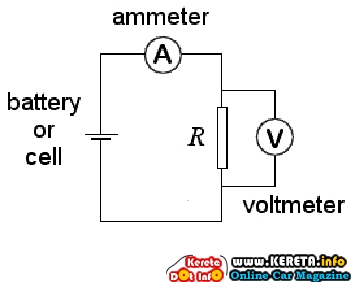
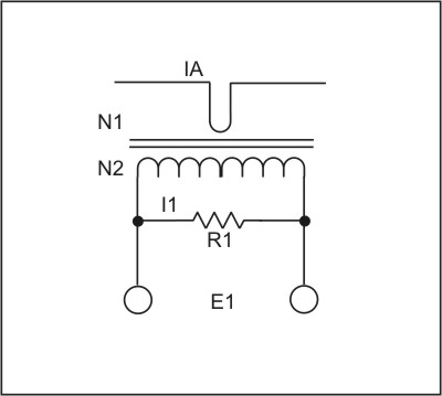
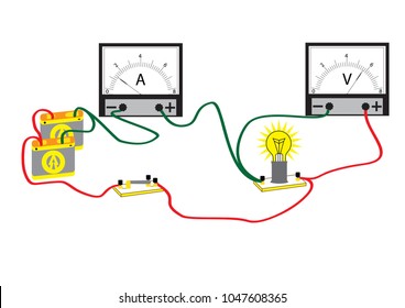
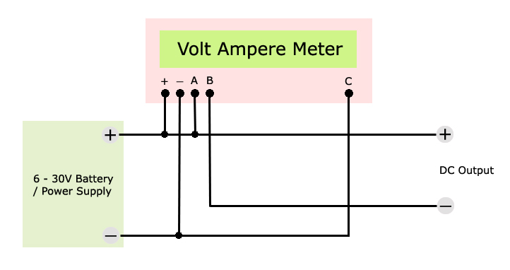
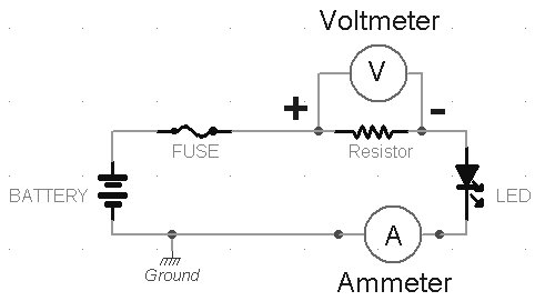
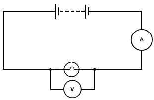
Ampere meter connection diagram. Ampere meter voltmeter connection electronics. An ammeter from ampere meter is a measuring instrument used to measure the current in a circuitelectric currents are measured in amperes a hence the name. In digital amp meter have 4 terminals or connection points in which two connection points for 220 voltage supply which operate the display circuit. A wiring diagram is a simplified traditional photographic representation of an electric circuit. This is a voltage and ampere measurement meter. Now i have included three most common variants of them.
It consists of guidelines and diagrams for various varieties of wiring methods and other items like lights home windows etc. Hers is a digital ampere meter circuit diagram with ct. They all have a bit different wire colors. Instruments used to measure smaller currents in the milliampere or microampere range are designated as milliammeters or microammetersearly ammeters were laboratory instruments which relied on the earths magnetic field for operation. Other 2 is for ct coil where we connect the current transformer wires. If you order digital 100v10a volt and ammeter gauge from china or other markets its most likely one of the following.
Two socket has in this meter. This meter can run 5 25 voltage. Building a 35kwh diy solar generator for 650. It reveals the elements of the circuit as simplified forms and the power and signal connections between the devices. 1st socket has 3 wire. How to make digital ampere meter connection how to do ammeter connection in urdu and hindi duration.
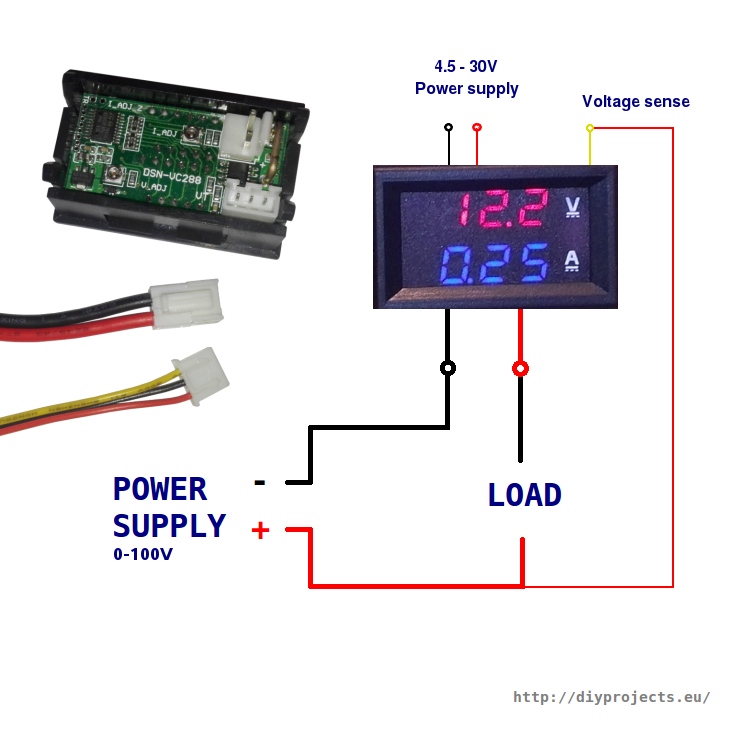
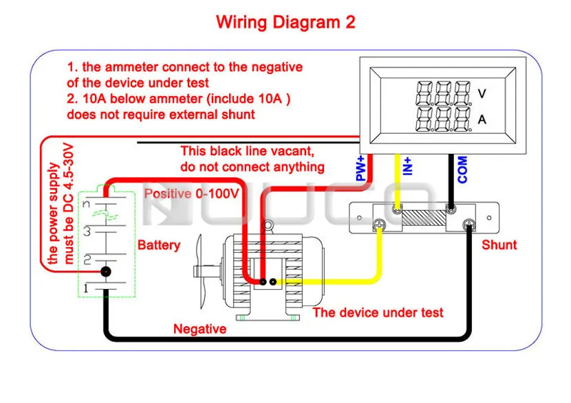
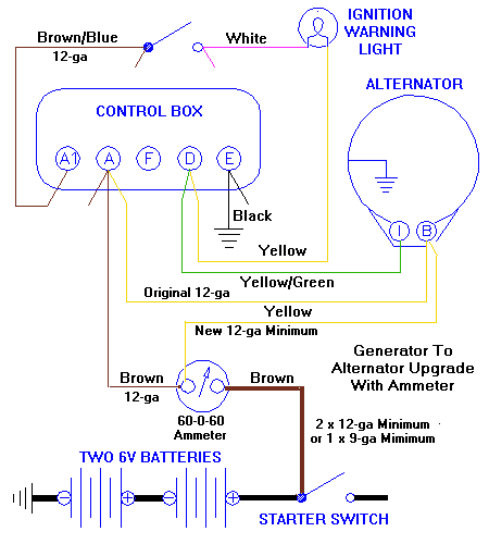
Assortment of volt amp meter wiring diagram. In the diagram above the wire colours shown in brackets refer to model tc0002. Red black and yellow. The original article included only one variant of these digital volt and ammeters. Ac amp meter wiring diagram manual e books digital volt amp meter wiring diagram wiring diagram consists of numerous in depth illustrations that present the relationship of various products. We can see it has 2 types of wire.
In this video we explain ammeter connection with selector switch and connection of current transformer as well. As you can see from the diagram both modules have 5 wire leads 2 for connection to meter power which must be in the range of 45 to 30v 2 for connection to the current shunt measuring terminals and 1 for the voltage measuring wire. We know we can connect single phase ammeter connection directly to the supply in.
