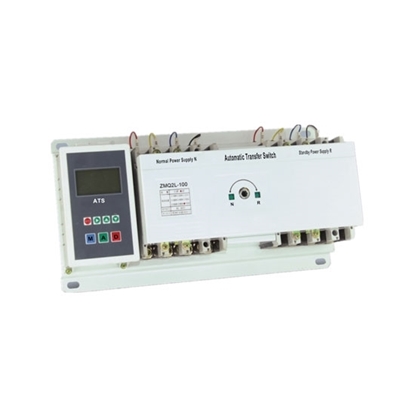
Superior design and robust construction make jundi electrical industry teco automatic transfer switch the industry. Ats gts line out doc 020 161 b0 rev.

Pdf Construction And Operation Of An Electronic Automatic
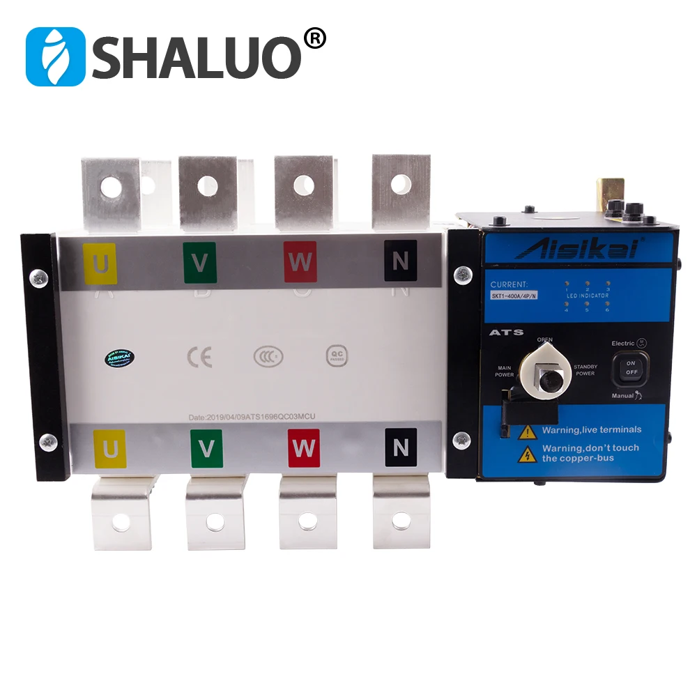
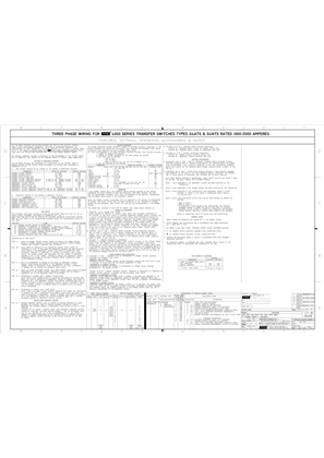
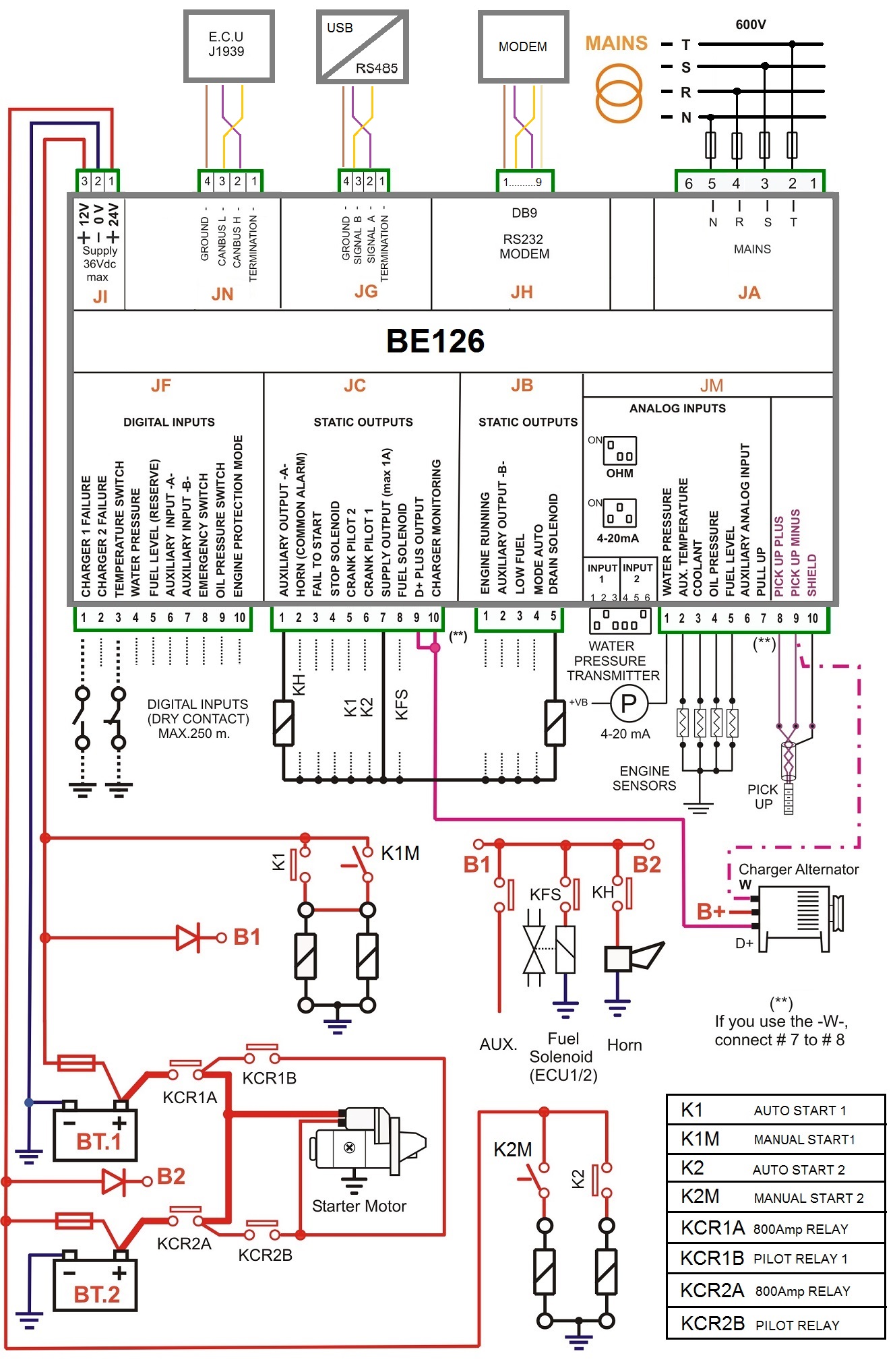
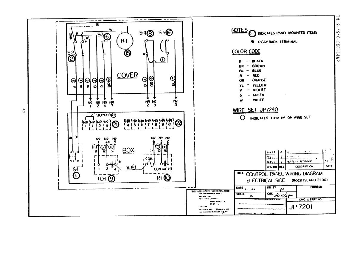
Ats panel wiring diagram pdf. For this purpose use only materials of suitable flammability class hb or better. The generator supply power to the. To the control panel cabinet. Connecting power conductors after the power cables have been tested connect them to the appropriate terminal lugs on the transfer switch as shown on the wiring diagram provided with this series 300. 01 07. Gts fxm family fxm family fig 3.
In the automatic changeover switch for generator circuit diagram the contactors are indicated kg for generator and km for mains. This guide will help you to make by your own generator control panels for standby generator. If the upper andor lower cabinet entry cable holes are used to route wiring into the control panel always use a proper pipe fitting system by means of an appropriate conduit and junction box. May 2018 om manual for 600 1000a 480 vac 3 position open service entrance contactor based transfer switch figure 3. Ats panel wiring diagram pdf. The automatic transfer switch ats figure 21 and the generator transfer switch gts.
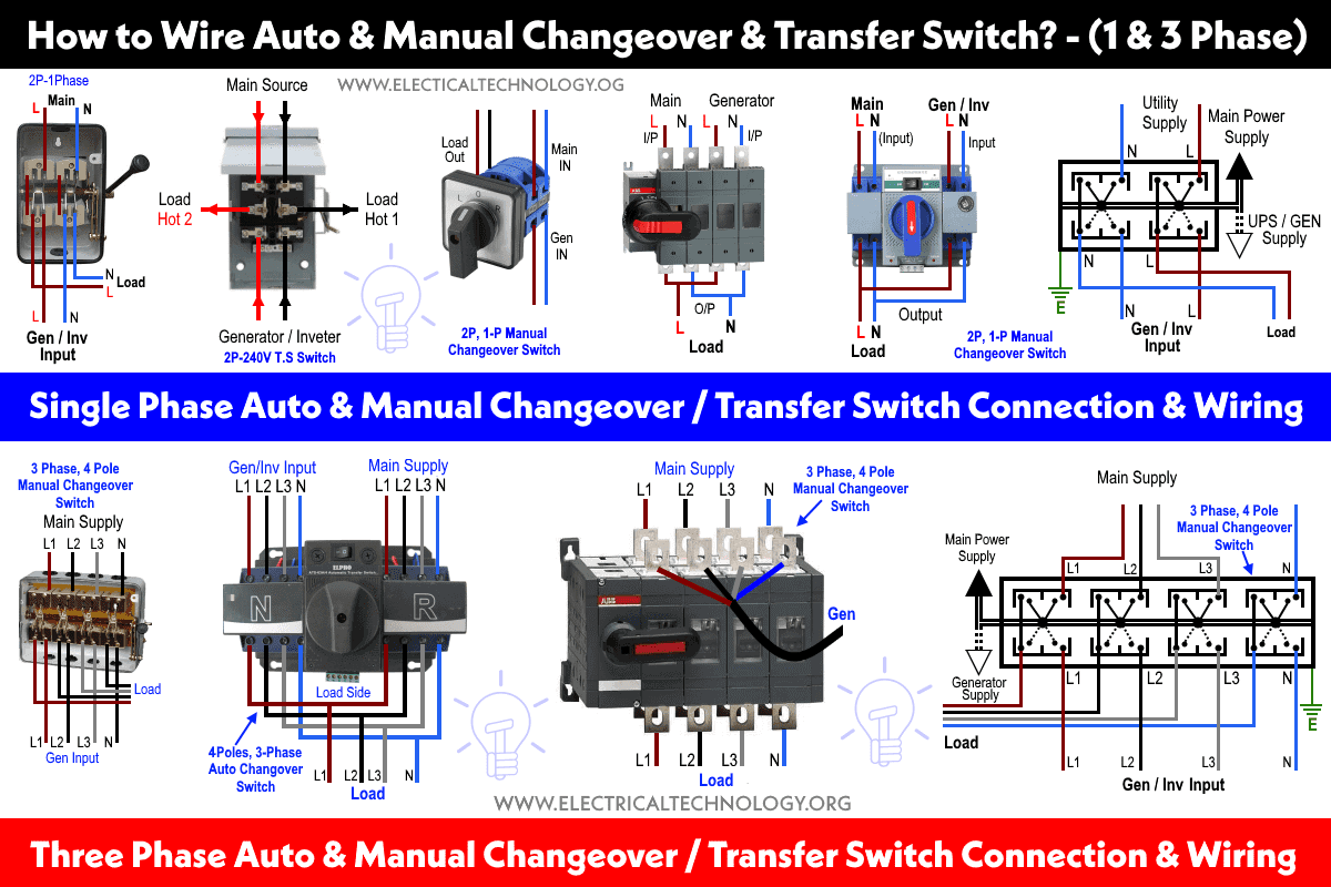
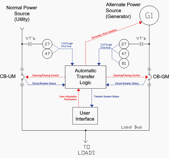
Ats when an electric utility outage occurs the ats will tell the backup generator to start. Once the ats sees that the generator is ready to provide electric power the ats breaks the homes connection to the electric utility and connects the generator to the homes main electrical panel. Panel voltage selectable transformer breaker neutral ground bond control panel for more information visit. In our step by step electrical wiring installation tutorials series we will show how to wire and connect single phase and three phase automatic and manual changeover and transfer switches to the home distribution board to use the backup power supply such us batteries power with ups and inverters or generator power in case of emergency breakdown and power outage. Ats ups fig 2. Wiring diagram fig 1.
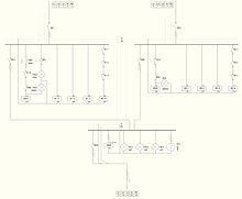
You will understand all details by following a step by step 60kva amf panel manufacturing. Typical service entrance open transition ats. Protect the automatic transfer switch from construction grit and metal chips to prevent malfunction or shortened life of the ats. Technical information 3 standard diagrams transfer between 2 sources 1 bus bar. 6 ats with sw1 cb1 on unit is in ups mode. Motorised switch cl ncl g q1 q2 ats automatic transfer switch protection arent shown on the following schemes summary.
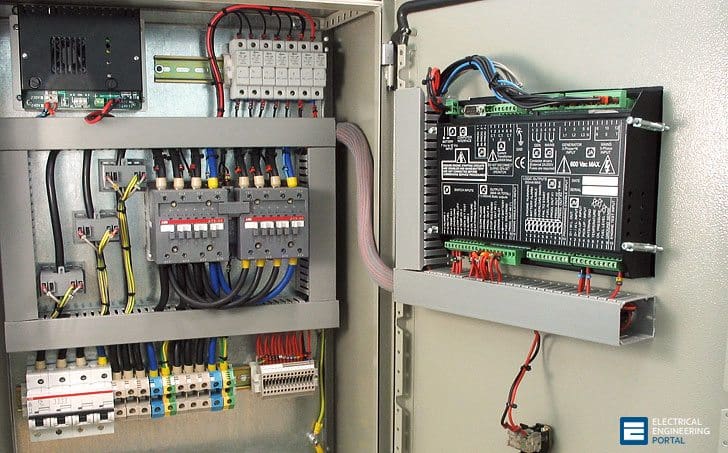
Breaker contactor or motorised switch socomec diagram. What others are saying ats panel control is the best option in situation wherever you have to control a power generator that is connected to the mains in a standby configuration. Wiring diagram asco series 300 automatic transfer switch ats 30 230 amps frame d single phase 718516 asco series 30.
