Internally this reset pin is the reset pin of the sr flip flop and hence the output of 555 timer is a low logic signal. This was a lot of fun to reverse engineer.
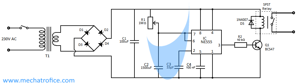
Auto Power Cut Off Timer Circuit
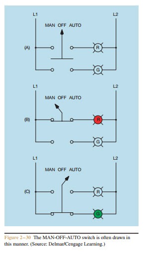
Auto switch circuit diagram. Where 0 represents the off condition and 1 represents the on condition. This circuit can be used for the automatic switchover of a load between a battery and a wall adapterltc4412 controls an external p channel mosfet to create a near ideal diode function for power switch over and load sharing. Kindly design another circuit which will sense the batter. This is a simple circuit where a n channel enhancement mode mosfet will turn on or off a light. I request you to kindly make a circuit which will sense that battery is getting discharged below certain threshold value say 180v esp during rainy season and should switch the input from solar to grid even though some amount of solar power is being generated. Learn how to access vehicle repair guides and diagrams through autozone rewards.
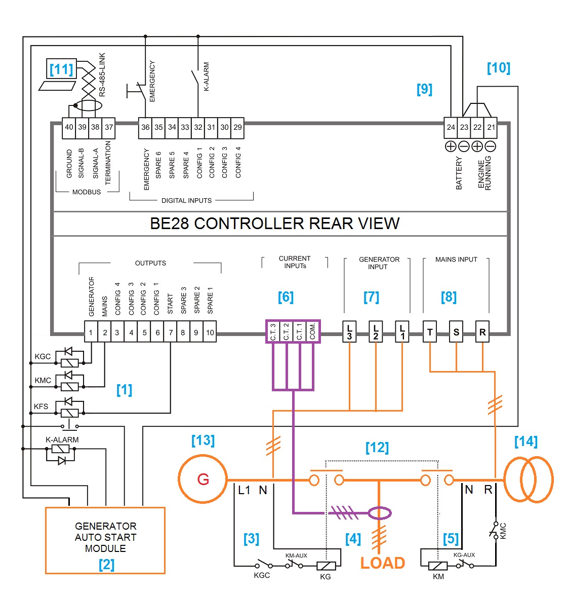
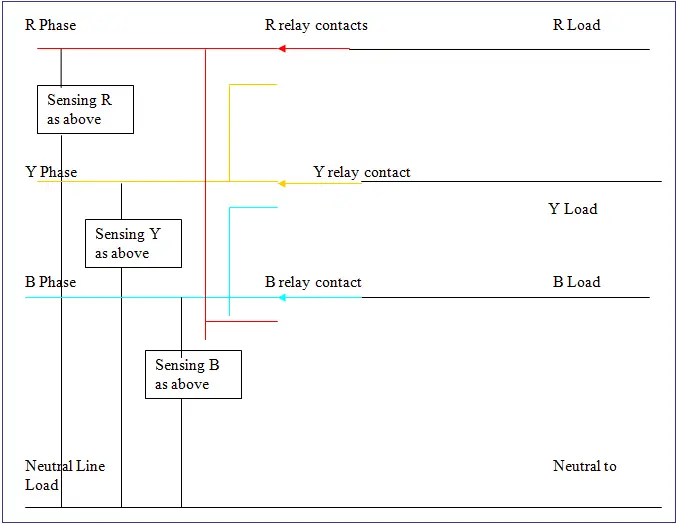
Its an automatic changeover switch for a backup generator supply. The circuit operation commences once the switch s1 is at any of its position. In order to operate a mosfet as a switch it must be operated in cut off and linear or triode region. Assume the device is initially off. Automatic changeover circuit operation. Each phase you have to use one module as above.
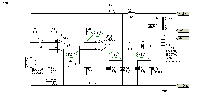
This method is commonly used now days as it is efficient than the two wire control system. The circuit diagram shows how it will be wired and here are the parts used. In our step by step electrical wiring installation tutorials series we will show how to wire and connect single phase and three phase automatic and manual changeover and transfer switches to the home distribution board to use the backup power supply such us batteries power with ups and inverters or generator power in case of emergency breakdown and power outage. D1 is a 35 amp 600 volt bridge rectifier t1 is a small transformer details in the text above d2 is a diode 1n4001 or similar to change the ac voltage from t1 to dc c2 is an electrolytic capacitor 100uf 50v d3 is a 10 volt zener diode keeps the voltage at or below 10vdc. This is the new method to make a 2 way switching connection as it is slightly different from the two wire control method. When the switch s1 is at position 1 reset pin of the 555 timer is grounded.
You can use a 100μf 40 volts good make in parallel with relay for chatter free operation. Set vr3 for minimum voltage to switch on the relay say 195 volt input. We will understand the operation of a mosfet as a switch by considering a simple example circuit. How to connect 2 way switch wiring using three wire control. Sign up today to access the guides. Mainly because its very old school inside.
When power fails and the generator starts. Set vr1 to switch off the relay above a particular voltage say 260volt input. The circuit diagram shown here is of a automatic changeover switch using ic ltc4412 from linear technologies.
Gallery of Auto Switch Circuit Diagram