Connect the ir sensors vcc and gnd pin to arduino 2. Automatic railway gate control system is accomplished to use various electronic components.
Automatic Railway Gate Control System With High Speed
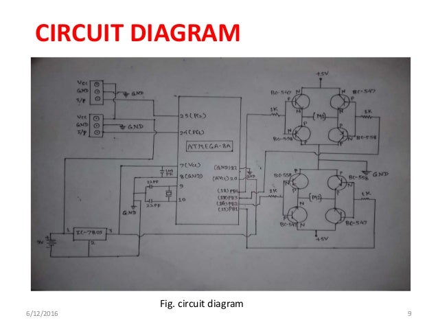
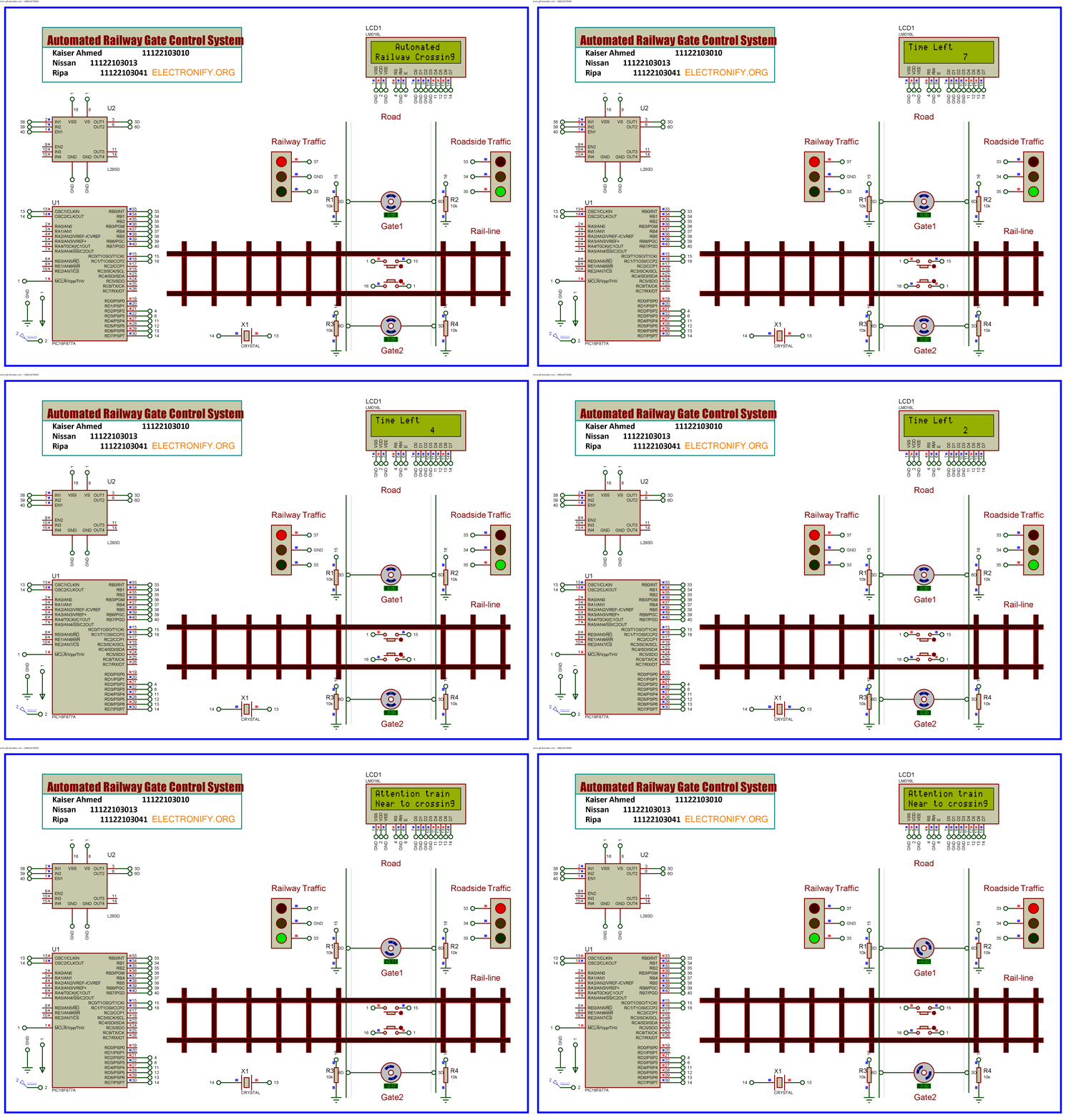
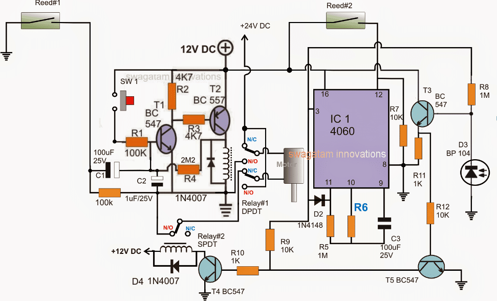
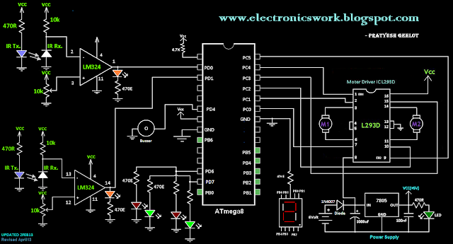
Automatic railway gate control circuit diagram. Connect all the connection as shown in circuit. Circuit 2 automatic railway gate controller with high speed alerting system. Nowadays many accidents take place at the railway gate crossing due to uneven crossings even when the gate is about to close. One is for the arduino nano which works as controller of the whole project. It has detectors at the far away distance on the railway track which allows us to know the arrival and departure of the train. Circuit diagram is shown in pic.
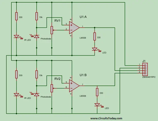
The other two pcbs are needed for the ir pairs. Automatic railway gate control system with high speed alerting system is an innovative circuit which automatically controls the operation of railway gates detecting the arrival and departure of trains at the gate. Connect the pin no 4 and 5 of arduino to l293ds input pins as shown in circuit. An automatic railway gate control system is implemented to prevent accidents of the traction system at the railway crossing levels. Automatic railway gate control system with high speed alerting system is an innovative circuit which automatically controls the operation of railway gates detecting the arrival and departure of trains at the gate. I designed all the three pcbs on eagle cad software.
The detail circuit diagram of the railway gate control system is shown. Connect the motor as shown in circuit. Automatic railway gate control system using microcontroller circuit. The input the processing and the output units. This system composed of. This system can be simply divided into three main categories.
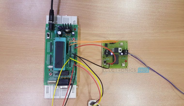
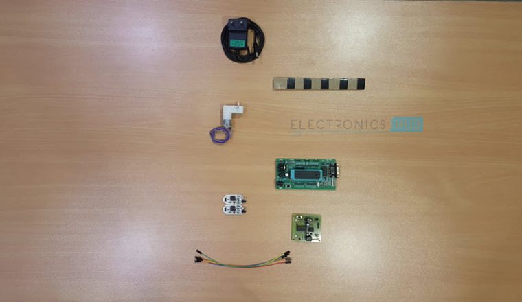
The automatic railway gate control makes use of 3 pcbs. The circuit diagram code component list documentation and other information. Connect the output pins of ir sensors to arduinos pin no 2 and 3 3.

