Accessing the circuit breakers performing maintenance on circuit breakers or any electrical circuits powered by them performing any operation where openingclosing the circuit breaker could be dangerous during maintenance. Switch and the tungsten load does not exceed 30 percent of the switch rating.

Pictures On Socomec Ats Wiring Diagram
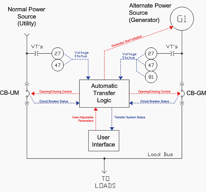
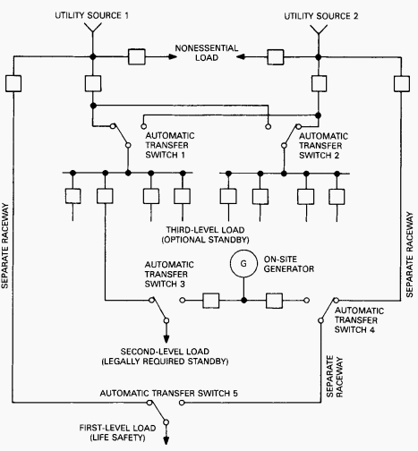
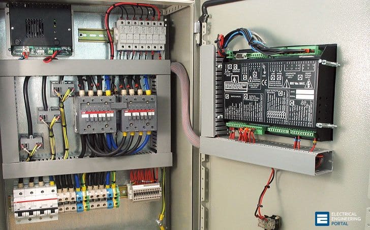
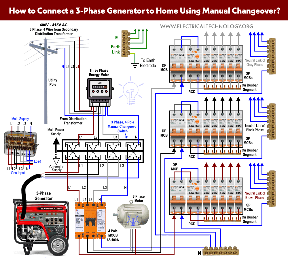
Automatic transfer switch circuit diagram pdf. 13 automatic transfer switch components there are three 3 basic components of a transfer switch. Switch has two inputs and one output and automatically transfers the available ac power to output. The transfer switch consists of a transfer mecha nism service disconnect circuit breaker a relay control fuses and a terminal strip for connection of sensing wires. Breaker contactor or motorised switch socomec diagram. It is also shows the working and operation for different changeover switches wiring connections like single phase manual changeover switch with generator three phase manual transfer switch connection with generator as well as single phase and three phase automatic transfer switches connections to the 1 and 3 phase generators and main fuse board. Technical information 3 standard diagrams transfer between 2 sources 1 bus bar.
The automatic transfer switch ats022 must be prevented from operating the circuit breakers before. Accessing the circuit breakers performing maintenance on circuit breakers or any electrical circuits powered by them performing any operation where openingclosing the circuit breaker could be dangerous during maintenance. Between agenerator and the shore or between an inverter and a generator or between an inverter and the shorethe transfer. This transfer switch is suitable for use as service entrance equipment. Assortment of generac 200 amp automatic transfer switch wiring diagram. The transfer switch is designed to take over automatic switching between different power sources.
121 transfer switch mechanism these switches figure 11 are used with a single. 2 transfer logic controller to monitor the condition of the power. A wiring diagram is a simplified standard pictorial depiction of an electrical circuit. This ul listed transfer switch is for use in optional standby sys tems only nec article 702. Motorised switch cl ncl g q1 q2 ats automatic transfer switch protection arent shown on the following schemes summary. This transfer switch is suitable for use on a circuit capable of 22000 rms 200a and 10000 100a symmetrical amperes 240 vac maximum.
The automatic transfer switch ats021 must be prevented from operating the circuit breakers before. 1 power switching device to shift the load circuits to and from the power source contactors changeover or circuit breakers. They transfer power automatically to the generator source and switch back to utility power when it is restored. A variety of automatic home standby transfer switches are available for use with generac automatic home standby generators.

