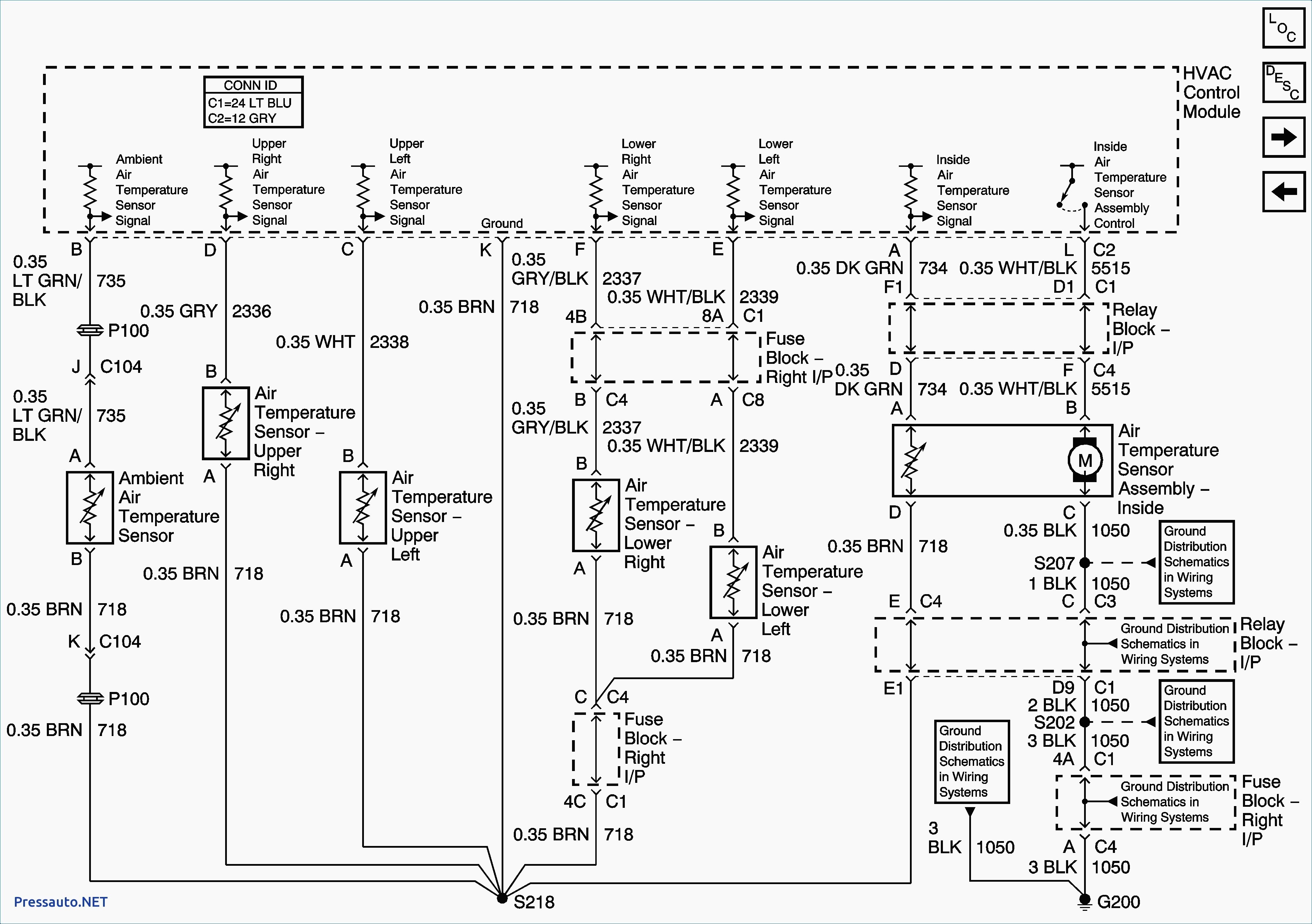
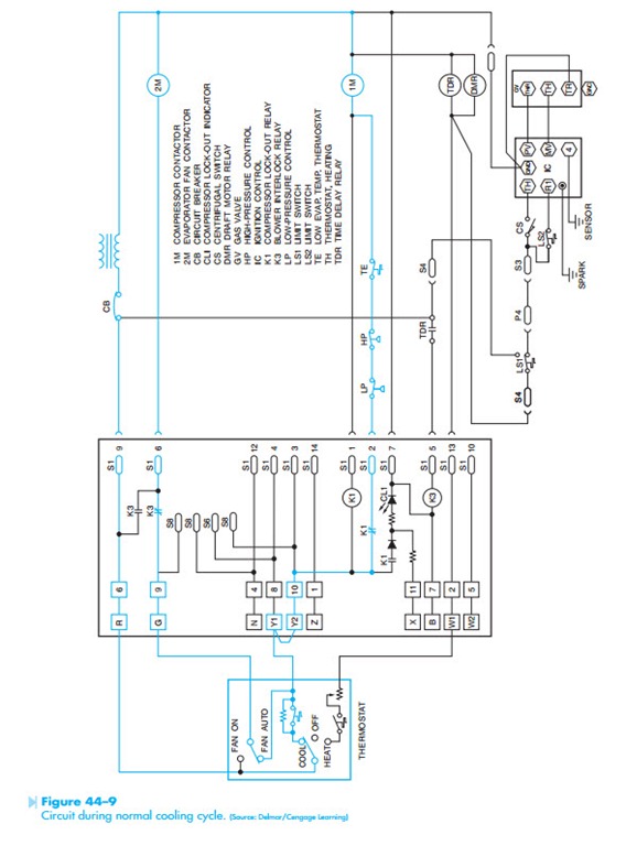
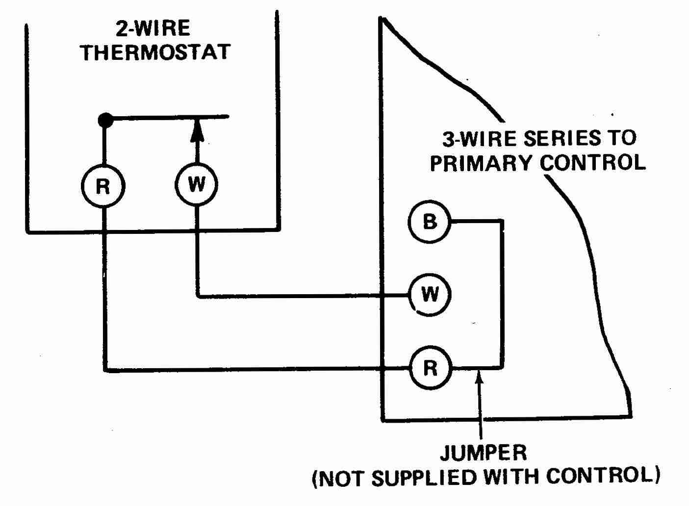
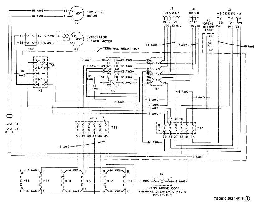
How to wire an air conditioner for control 5 wires the diagram below includes the typical control wiring for a conventional central air conditioning systemfurthermore it includes a thermostat a condenser and an air handler with a heat source. Central air conditioner wiring diagram central air conditioner wiring diagram collection carrier air conditioning unit wiring diagram fresh ac unit.

Adding Freon Window Air Conditioner Wiring Diagram Fusebox
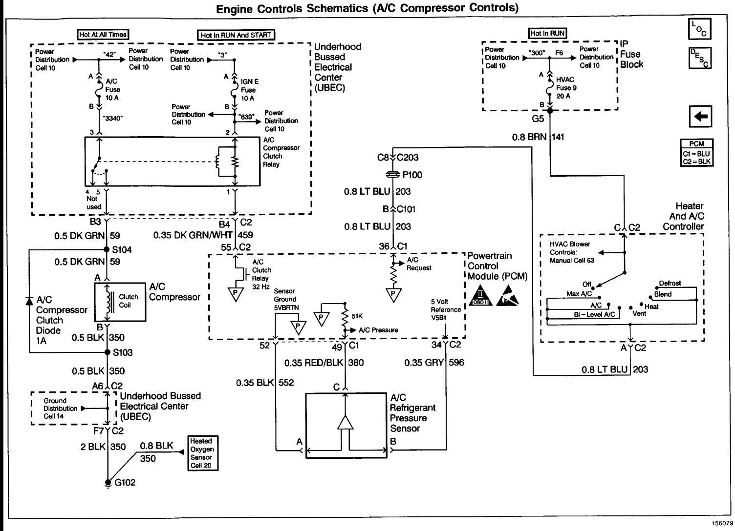
Basic air conditioning wiring diagram. Designed for ac repair technicians. Car air conditioning wiring diagram wiring diagrams ac wiring i need help guys third generation f body message boards car air conditioning wiring diagram wiring diagrams. Talks about basic electrical wiring and components in a straight cool split type air conditioner. A c unit wiring diagram wiring diagram origin basic air conditioner wiring diagram schematic wiring diagrams. Note some ac systems will have a blue wire with a pink stripe in place of the yellow or y wire. It is better to take a good up close photo of the old thermostat and what terminals the colored wiring are terminated.
Basic auto air conditioning wiring diagram how to ac compressor clutch relay parts. Batter ac selector switchblower motor aux fan motor compressor catch coil resistor block fuse compressor. Usually the electrical wiring diagram of any hvac equipment can be acquired from the manufacturer of this equipment who provides the electrical wiring diagram in the users manual see fig1 or sometimes on the equipment itself see fig2. Basic thermostat wiring colors air conditioner systems always remember when changing a thermostat for a new thermostat to take a photo of the colors and where they go on the old thermostat or get a pencil and paper and write it down. 2 how to get the electrical wiring for air conditioning systems. Always refer to your thermostat or equipment installation guides to verify proper wiring.
Moreover the heat source for a basic ac system can include heat strips for electric heat or even a hot water coil inside the. Also details how the parts work and how the electrical works. After that the main power cord of the split air conditioning unit is connected to this disconnecting means from one side the other side is connected to the terminal box in the indoor unit see fig9 or in the outdoor unit see fig10according to the manufacturers recommendations and wiring diagrams. Air conditioning ac contactor control board 1 this diagram is to be used as reference for the low voltage control wiring of your heating and ac system. The metering device component 3 on this air conditioning circuit and cycle diagram is the dividing point between the high pressure and low pressure sides of the system and is designed to maintain a specific rate of flow of refrigerant into the low side of the system.


