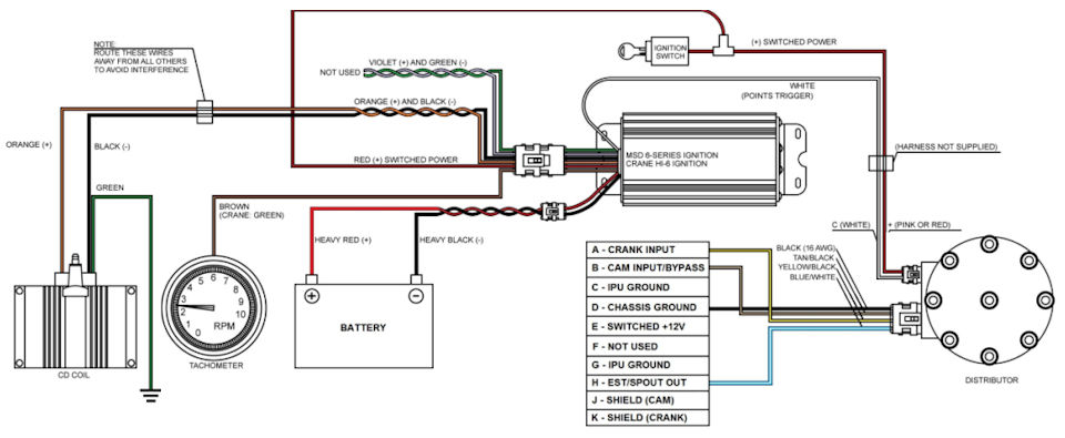
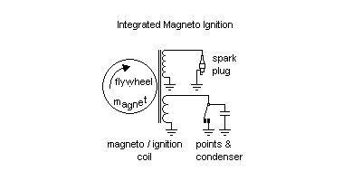
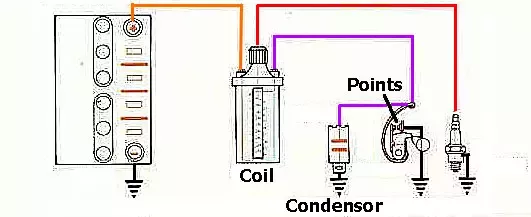
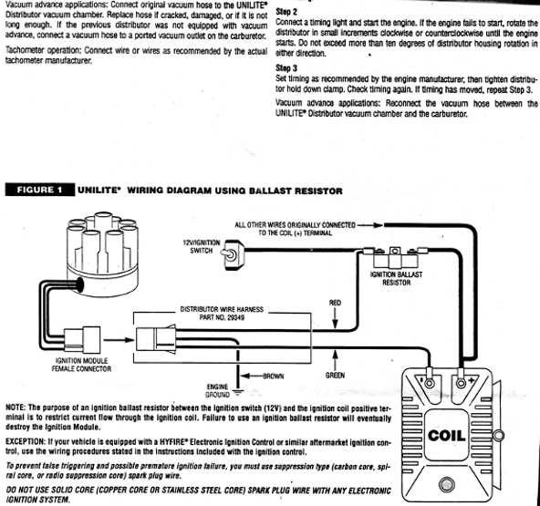
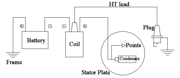
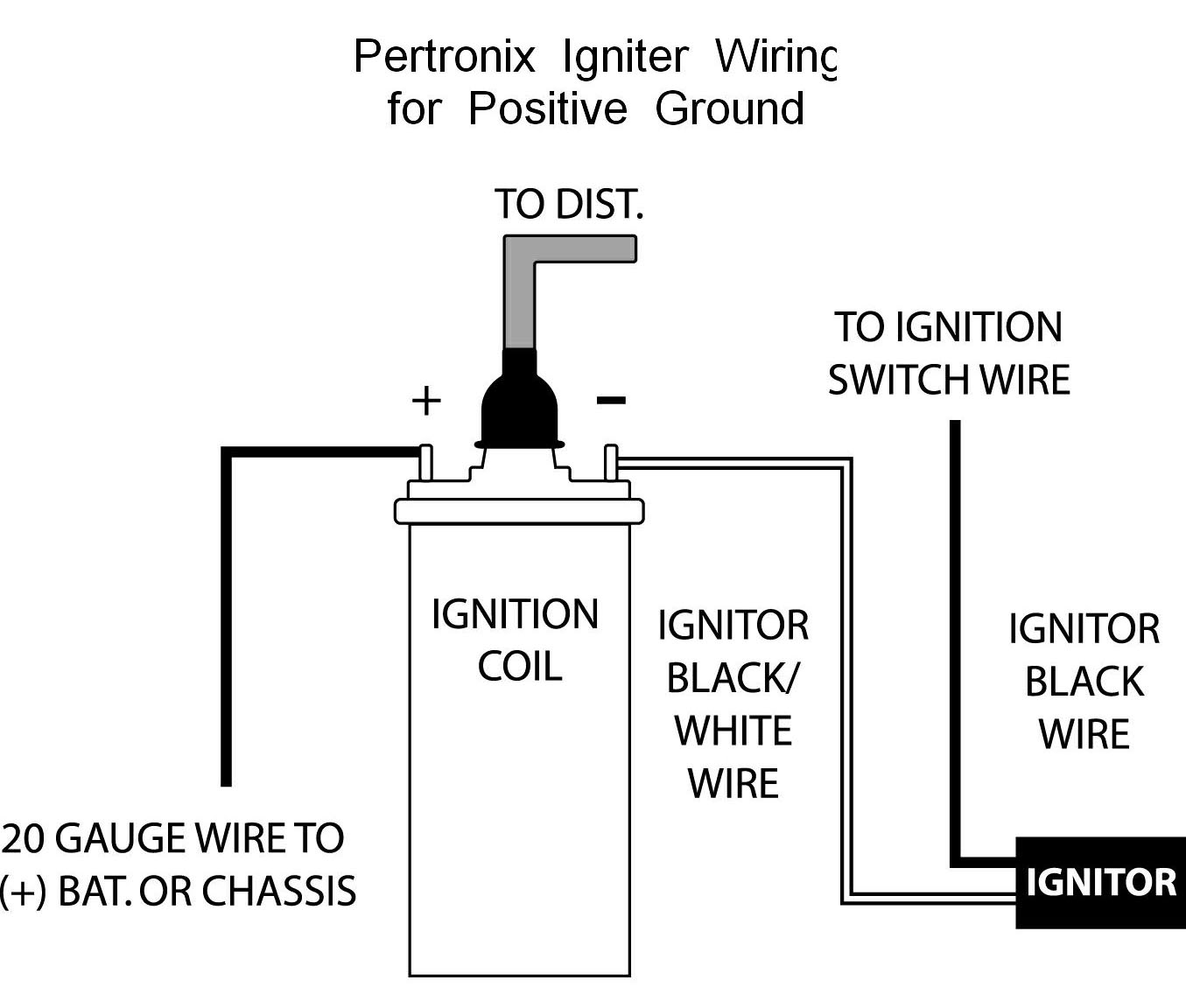
Basic points ignition wiring diagram wiring diagram is a simplified satisfactory pictorial representation of an electrical circuitit shows the components of the circuit as simplified shapes and the power and signal connections between the devices. When the points are touching each other electricity runs from the battery through the coil and to the engine block which is grounded to the negative terminal on the battery.

Understanding Breaker Point Ignition Systems Gas Engines
Basic points ignition wiring diagram. A schematic diagram of an electronic ignition system is shown in figure 236. The current running through the windings in the ignition coil builds up a powerful electrical field that is unleashed when the points separate. Automotive wiring diagram resistor to coil connect to distributor wiring diagram for ignition coil. This is a image galleries about basic ignition wiring diagramyou can also find other images like wiring diagram parts diagram replacement parts electrical diagram repair. Where do i find a basic wiring diagram for a breaker points ignition system. Each part ought to be placed and linked to other parts in specific way.
For more information on the individual components in a pointscondenser ignition system see the separate articles in the components explained section. Points and condenser wiring diagram briggs and stratton points and condenser wiring diagram points and condenser wiring diagram points condenser coil wiring diagram every electric arrangement consists of various different components. Construction of electronic ignition system. It consists of a battery ignition switch electronic control unit magnetic pick up reluctor or armature ignition coil distributor and spark plugs. In a 4 stroke 4 cylinder engine as shown in the diagram for every 1000 revolutions of the engine the ignition cycle will be completed 2000 times. Otherwise the arrangement wont work as it ought to be.

