The stator is typically comprised of steel laminations slotted axially to accommodate an even number of windings along its inner periphery. The esc needs a powers source of around 12v and 5a minimum.
1 3 2 Brushless Dc Motor Nidec Corporation
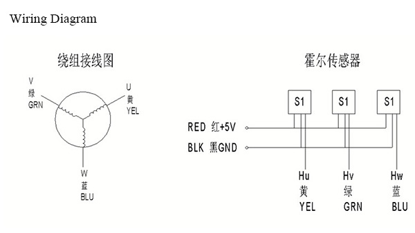
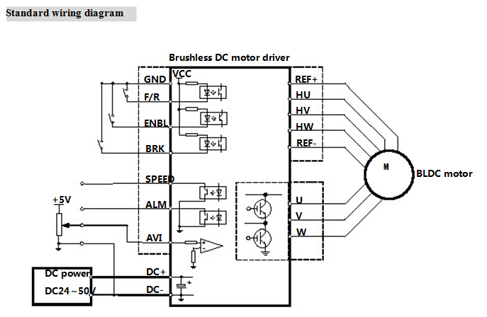
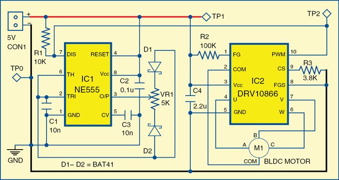
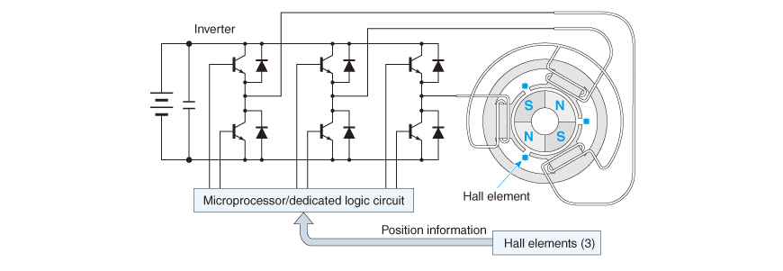
Bldc motor connection diagram. In this tutorial i have used my rps as a power source but you can also use a li po battery to power the esc. It shows the elements of the circuit as simplified forms as well as the power as well as signal connections between the gadgets. Figure 1 is a simplified illustration of bldc motor con struction. The windings become the stator and the permanent magnets become part of the rotor. You just have to hook up the shown elements in place and use the design to operate any bldc motor with sensors rated within 8v to 50v at 3 amps rate. To verify that this is the correct wiring diagram for your bodine product please check for the connection diagram reference number in the specifications table on the applicable itemmodel page.
Arduino bldc motor control circuit diagram the connection for interfacing bldc motor with arduino is pretty straight forward. Click download pdf to view this wiring diagram. A brushless motor is constructed with a per. Sensorless bldc motor control using a majority function part 1 duration. A bldc motor overcomes the requirement for a mechanical commutator by reversing the motor set up. A brushless dc motor known as bldc is a permanent magnet synchronous electric motor which is driven by direct current dc electricity and it accomplishes electronically controlled commutation system commutation is the process of producing rotational torque in the motor by changing phase currents through it at appropriate times instead of a.
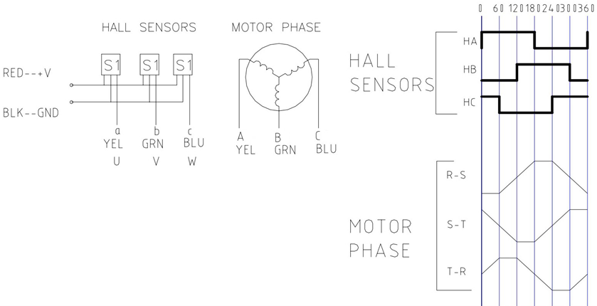
The static alignment shown in figure 2 is that which would be realized by creating an. 50v bldc driver circuit diagram a typical l6235 50v 3 phase bldc motor driver circuit application can be witnessed above which looks quite straightforward with its implementation procedures. Construction of bldc motor. A timing diagram. How to make servo tester esc tester. Diy servo esc controller circuit.
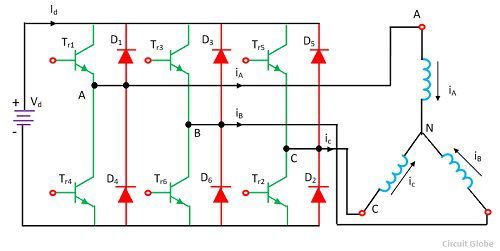
The main design difference between a brushed and brushless motors is the replacement of mechanical commutator with an electric switch circuit. Three phase winding topology with star connection. Keeping that in mind a bldc motor is a type of synchronous motor in the sense that the magnetic field generated by the stator and the rotor revolve at the same frequency. A motor with this topology is driven by energizing 2 phases at a time. Collection of bldc motor controller wiring diagram. Connection diagram for 230460vac 9 wire reversible 3 phase gearmotors and motors 07410012.
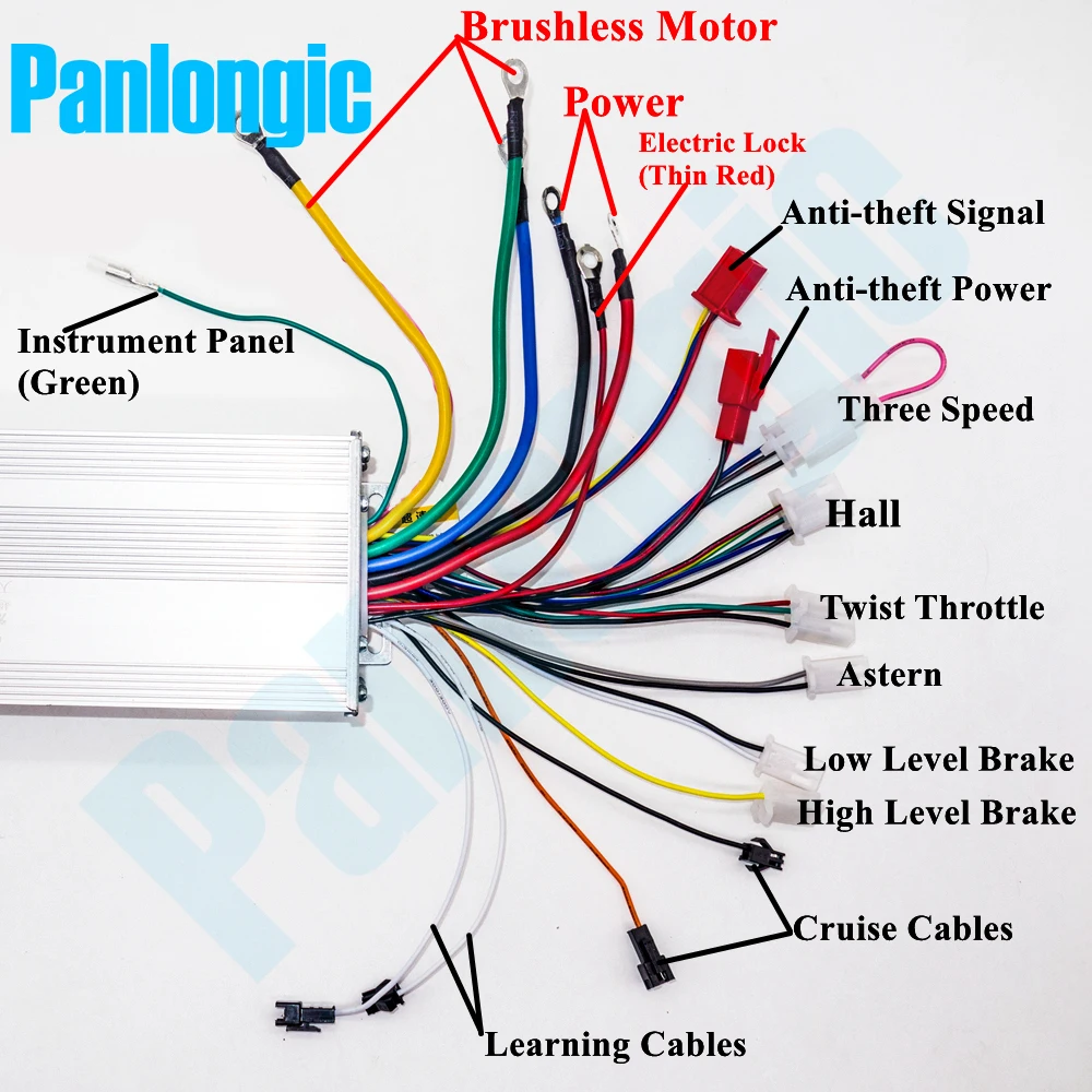
Rs components 90420 views. How to find wire functions of bldc controller which dont have labels on wires duration. A wiring diagram is a streamlined standard pictorial representation of an electric circuit. What is a brushless motor and how it works torque hall effect 3d animation.
