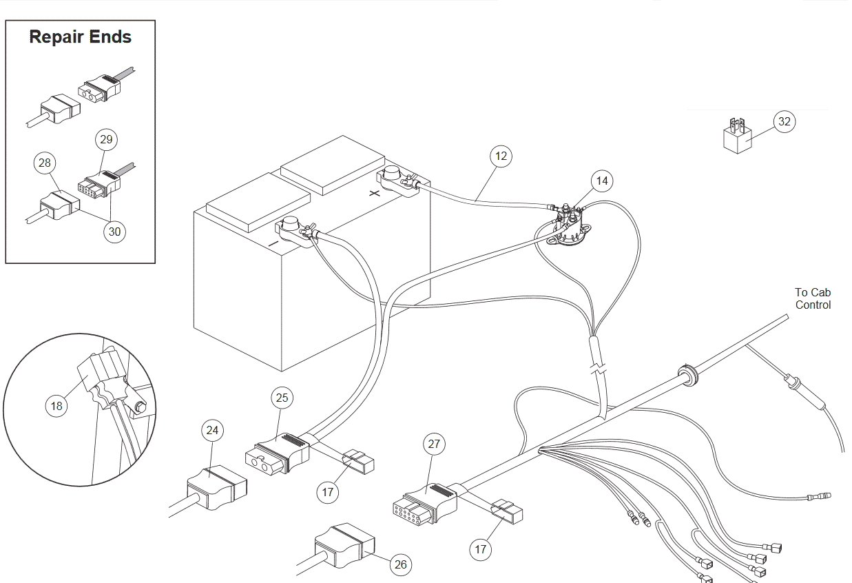
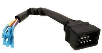
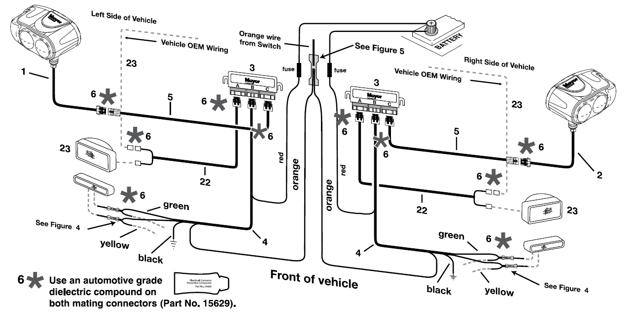
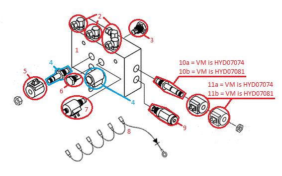
Straight blade harness wiring diagram g10074 color function pin black 12 volts 1 orange plow down 2 white plow up 3 red right 4 green left 5 blue left 6 yellow right 7 purple pump solenoid 8 brown ground 9. If you have further questions your local boss plow dealer is the person to talk to.

Boss V Plow Wiring Schematic Fuse 10 Brillenstudio Weichert De
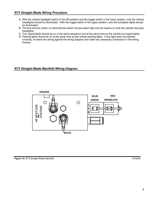
Boss straight blade plow wiring diagram. This and the straight position are not effective for carrying large. Place plow blade 4 face down on the box. The box can be used as a mat and will help prevent scratching the blade during installation. Place plow blade 4 face down on the box. Straight blade manifold wiring diagram power v wiring schematic straight blade wiring schematic. Corner of the plow box so that each wall of the box will lie flat on the floor.
Install msc01570 cast shoe assembly 12. Mount plow shoes 12b on blade assembly 4 using 1 12 spacer 12d and 1 flat washers 12c on the bottom and top of the shoe. Rt3 power v blade with smarthitch wiring diagram figure 5. Install cast shoe assembly 12. Microsoft word joystick wiring schematic str bladedoc. Intercon truck equipment 1200 pauls lane joppa md 21085 tel.
Harness wiring diagram figure 1. Secure with 716 quick pins 12a. Mount plow shoes 12b on blade assembly 4 using 1 12 spacer. In general plow shoes should be mounted.


