As soon as the power is turned on the current flows through these internal connections. Because the solderless breadboard does not require.
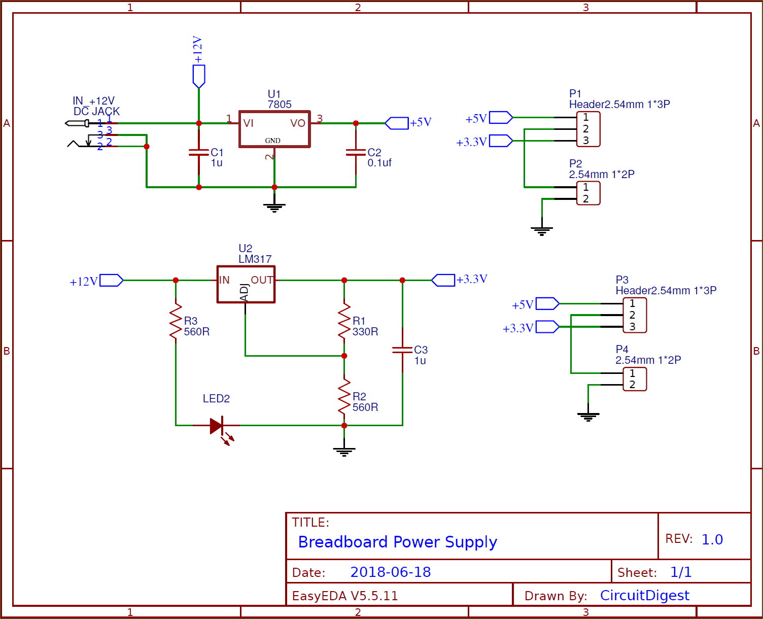
Diy Breadboard Power Supply Circuit On Pcb
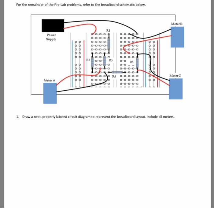
Breadboard connection diagram. The power supply is connected to these rows at the top and 0v zero volts at the bottom. Unlike a circuit diagram or a schematic which use symbols to represent electronic components. The following tutorial translates from a circuit diagram to actually connecting components on a breadboard. Books on line resources and materials use them to communicate the circuit connections. This is a more advanced technique and it requires some. Another method of using the binding posts is to solder a barrel jack to some wires and then connect them to the binding posts.
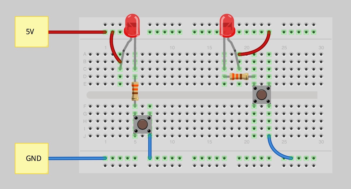
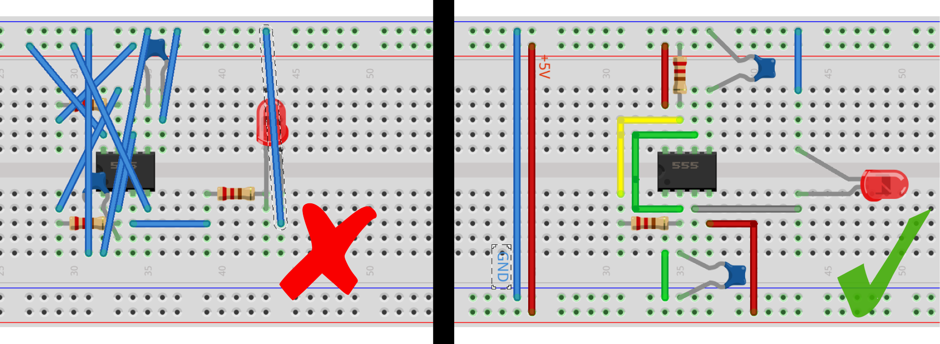
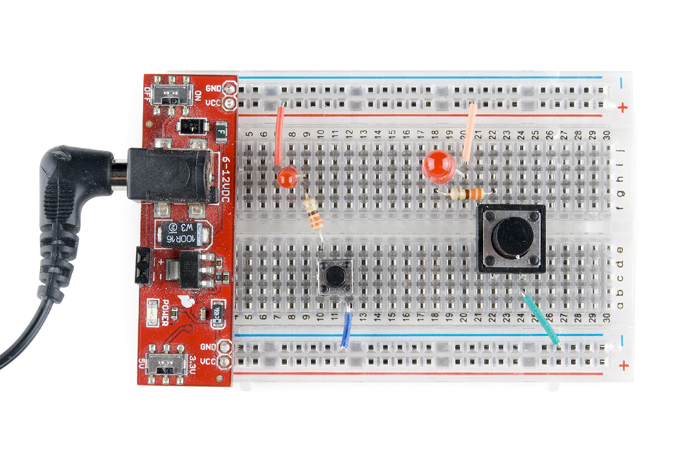
A breadboard diagram is a computer generated drawing of a circuit on a breadboard. The top and bottom rows are linked horizontally all the way across as shown by the red and black lines on the diagram. In the 1970s the solderless breadboard aka. In the new edition of the arduino cookbook michael margolis gives a great step by step explanation of how to read a schematic and build a breadboard prototype from itthe following excerpt is adapted from appendix b of the cookbook. Note that the circuit diagrams are the universal way of representing circuits. A breadboard is a solderless device for temporary prototype with electronics and test circuit designs.
A schematic diagram also called a circuit diagram is the standard way of describing the components and connections in an electronic. The diagram shows how the breadboard holes are connected. The easiest way to get started with building a breadboard circuit is by following a breadboard diagram. In the below diagram you can see both the vertical columns and horizontal to be connected internally. See the advanced section to learn more breadboard diagrams make it easy for beginners to follow instructions to build a circuit because they are designed to look like. Plugboard a terminal array board became available and nowadays the term breadboard is commonly used to refer to these.
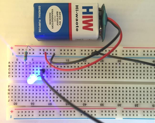
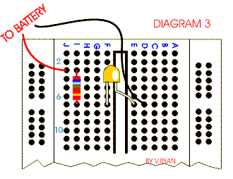
The below figure shows the internal connections of component rails and power rails. Alternatively you could use alligator clips ic hooks or any other cables with a banana connection to hook your breadboard up to a number of different supplies. Let us know breadboard connections basics such as how the rails are connected internally. They are very useful compared with pictorial diagrams of the connections. The breadboard has strips of metal underneath the board. A 9 volt battery is eventually attached to the led light.
In the below diagram you can see how a resistor of 380 ohm and a led are set up on the breadboard. A breadboard is a construction base for prototyping of electronicsoriginally the word referred to a literal bread board a polished piece of wood used for slicing bread. Heres what you need. Now that youve understood how to establish a simple breadboard circuit connection heres a tutorial to help you get started with building a breadboard circuit with leds. Most electronic components in electronic circuits can be interconnected by inserting their leads or terminals into the holes and then making connections through wires where appropriate. The conductive layout diagram of the breadboard is shown in the figure above.


