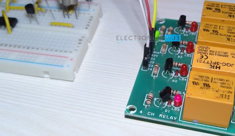
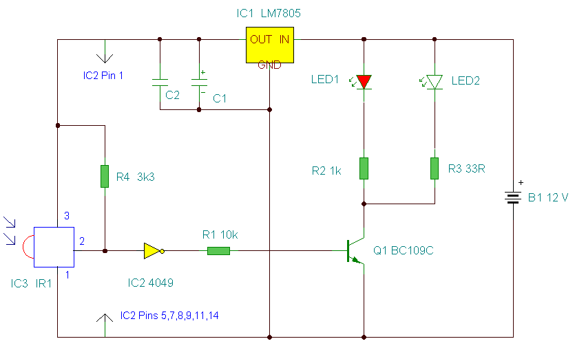
The infrared remote control switch is divided into two sections. Before wiring the circuit make sure that the carrier frequency of the tv remote you have is 38 khzfor that wire the sensor part only point your remote to the tsop1738 and press any switchif out put of tsop1738 goes low then ok your remote is of 38khz typenothing to worry almost all tv.

Wf 9756 Simple Remote Control Car Wiring Diagram Wiring Diagram
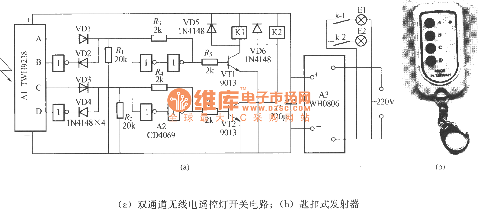
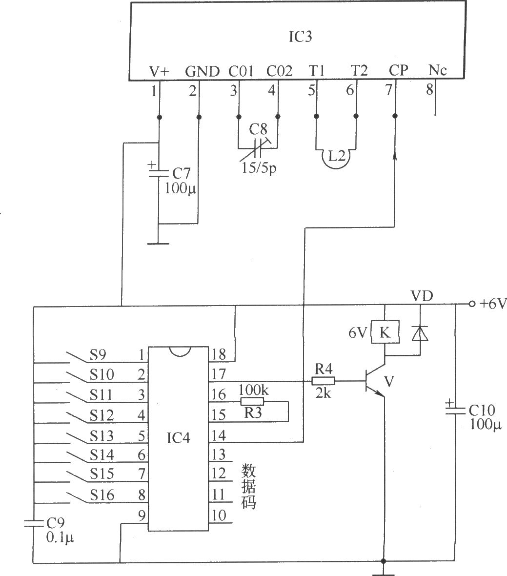
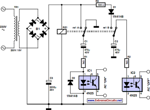
Circuit diagram of remote control switch board. If your circuit does not work even after making on pcb try some nearest upper and lower values for r1rx or connect a 500k pot and fine tune it until you got a matched frequency. Remote controlled switch circuit diagram notes. The circuit diagram below is mostly the same. Circuit diagram of infrared remote control switch. Transmitter section and receiver section. In the receiver section there are 3 photodiodes which will detect the infrared signals from the receiver and produce leakage current to the capacitor c1.
It uses a tsop1738 ir receiver module at the input side to receive the 38 khz frequency ir pulses from the remote control. Receiver circuit is connected to ac appliance via relay so that we can control the light remotely. Ir remote controls switch circuit. Under normal condition the output pin of the ir module is at logic high which means the transistor t1 bc558 pnp is cut off and its collector terminal is at logic low. The ca 3130 op amp is a bicmos operational amplifier and it has a high input impedance a low input current and a high speed performance. The main components of this ir remote control switch are ca 3130 operational amplifier and 4018 counter.
This current is given to the inverting input of 3130 ic which will get triggered by this current and give amplified output. In this remote controlled switch circuit we are using tv remote to onoff the ac light by pressing any button of remote and using the tsop1738 at receiver end. We have used ic 4017 to convert it into a push on push off switch.


