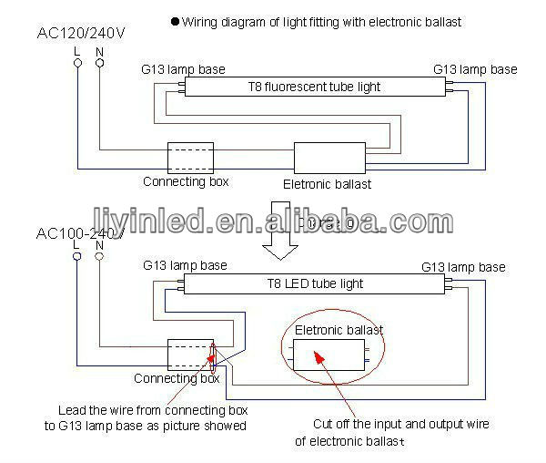
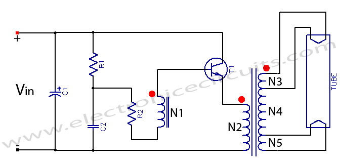
The circuit diagram shown above is quite simplified from basic tube light wiring diagram by adding a bridge rectifier. Connection of tube light is very simple because it has few wiring points only.

19 Unique T8 Led Tube Light Circuit Diagram
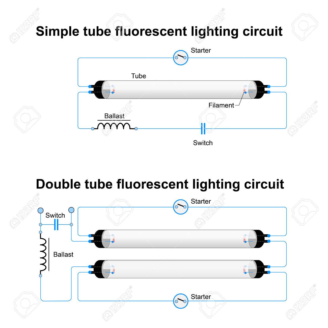
Circuit diagram of tubelight. Tube lights are most used light source and here tube light connection circuit and wiring diagram given with explanation. Using this circuit you can glow tubelight for extra six month. We need tube light ballast starter and fluorescent. In this video we have changed the original dead circuit of led tube light and replacing with ballast circuit. Please see circuit diagramfor converting ac to dc we have used a rectifier circuit. Please let meknow 2.
Tubelight circuit diagram fluorescent light working principle working of fluorescent light tubelight working principle connection and working. The first is the minimal power factor circuit along with the other works with a novel diodecapacitor settings to accomplish a power factor 095. 2150 leds over load protection is there am i right. How to install a single tubelight with electromagnetic ballast. Bridge rectifier provides high voltage dc to the both end of tube. The lower power factor circuit proven in figure 3 welcomes 115 vac or 230 vac 5060400 hz inputs to generate a moderate dc bus of 320 vdc.
Since the led tube lights are very costly an. The starter is like a key of fluorescent light because it is used to light up the tube. 1accoring to the 3rd circuit 150 led circuit how to connect 12v7ah battery pls let me know the changes of components or as represeted in the diagram. Electronic ballast has six ports two ports out of six ports are for the input and the remaining four ports are for output ports. All we have focused in this project is to lighting up the weak tube using high voltage dc. Overload protection to the batter 470 oms can be connected series to the d2 2nd diagram 24 leds.
Choke should be used in series with rectifier circuit for limiting currentrectified voltagedc is applied to both end of the tube. When we connect the ac supply voltage to the circuit then the starter act like short circuited and current flow through those filament located at the first and second end of the tube light and the filament generate heat and it ionized the gas mercury vapor in the fluorescent tube lamp. Twin 40 watt ballast circuit diagram. As no starter is used in the case of electronic ballast application the wiring diagram is slightly different. The tube light or fluorescent light is a low pressure mercury vapor gas discharge lamp and it uses fluorescent to produce white light.


