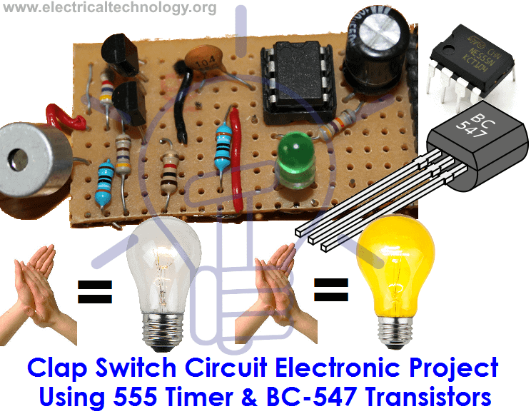
Reset low output low. Clap switch is a basic electronics mini project made with the help of the basic components.

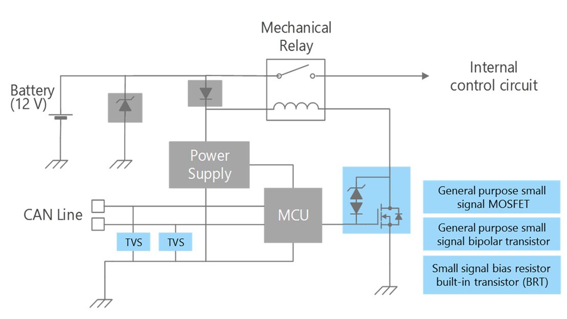
Voltage Clamp Wikipedia
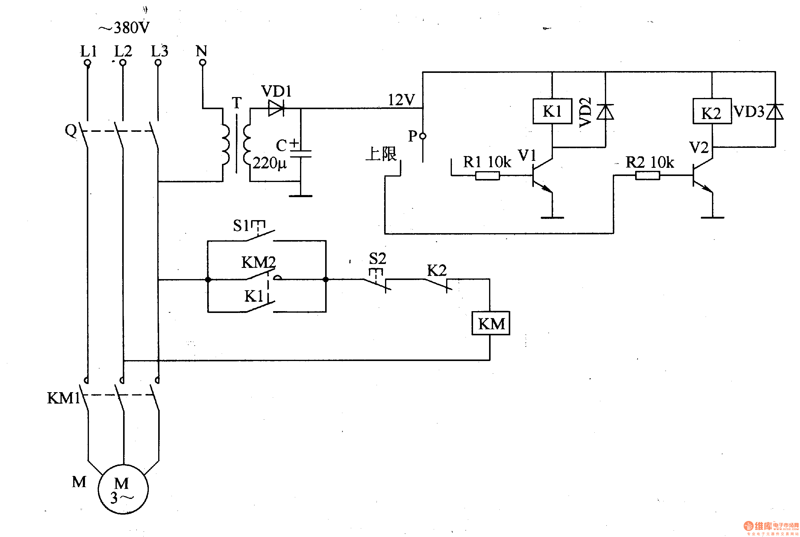
Clamp switch circuit diagram. Clap switch is an interesting hobby circuit which turns on the lights with a clap sound. Triggerresetlow output high. And next applied to the regulator circuit system. Block diagram circuit diagram arduino floor plans circuits clamp log projects floor plan drawing house floor plans. Our aim is to switch on the light for a particular time. Share on tumblr remote access to electrical devices are makes us comfortable and if you can control electric device with clap then it makes you very joyful and here we have prototype a simple clap on clap off switch using 555 timer and this circuit can help us to control any electric device here for an example we have taken electric bulb.
In simple trigger low output high. Clap switch circuit diagram using ic 555. But how switch mode power supply works. In this circuit we have two switches called trigger and reset. The transistor switch is a 2n3904 npn bi polar transistor good for 200ma at 40 volts. In this circuit 555 timer ic and 7474 dual positive.
Condenser mic basically converts sound energy into. This circuit is used for the manual on switch and to supply power for the transistor to energize the relay coil. And high frequencythis dc voltage is converted into a high frequency ac signal. It can produce 300ma at 6 volts. The main component of this clap switch circuit is the electric condenser mic which has been used as a sound sensor. Although its name is clap switch but it can be turned on by any sound of about same pitch of clap sound.
It keeps the voltage and current for a load. Clap switch is a basic electronics mini project made with the help of the basic components. With ic 555 timers and without 555 timer. Although its name is clap switch but it can be turned on by any sound of approximately same pitch of clap soundthe main component of this clap switch circuit is the electric condenser mic which has been used as a sound sensorcondenser mic basically converts sound energy into electrical energy. An auto pedestal level clamp circuit which clamps a pedestal level of a television signal input through a dc blocking capacitor using a pedestal level clamp switch to automatically adjust the pedestal level includes a level detecting circuit for detecting a luminance signal level of the television signal and an ad converter for judging a luminance of a frame based on the output from the. The main component of the circuit is the electric condenser mic which has been used as a sound sensor.
No transformerit converts the ac power directly into a dc voltage without a transformer. It works as a switch which makes devices on and off by making a clap sound. I put in a 6 volt zener voltage clamp in the input because of the 12 volts from the home made transformer. Introduction to clap switch circuit. Once the trigger is set to low the output will stays high until the reset set to low. Clap switch has the ability to turn onoff any electrical component or circuit by the clap sound.
We will use two basic clap switch circuit diagrams ie. Clap switch has the ability to turn onoff any electrical component or circuit by the clap sound.
Gallery of Clamp Switch Circuit Diagram