Single phase motors are used to power everything from fans to shop tools to air conditioners. Three phase motors with single phase frequency inverter should be used for frequent onoff switching.

Clarke Compressor Asd Wiring Passionford Ford Focus
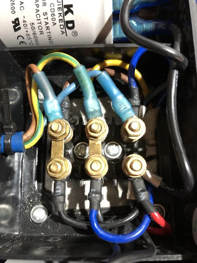
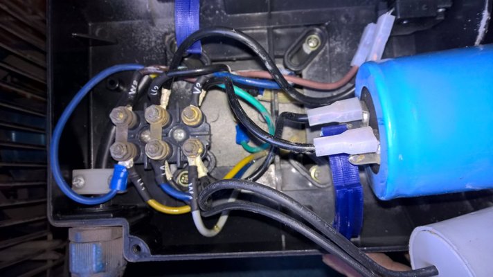
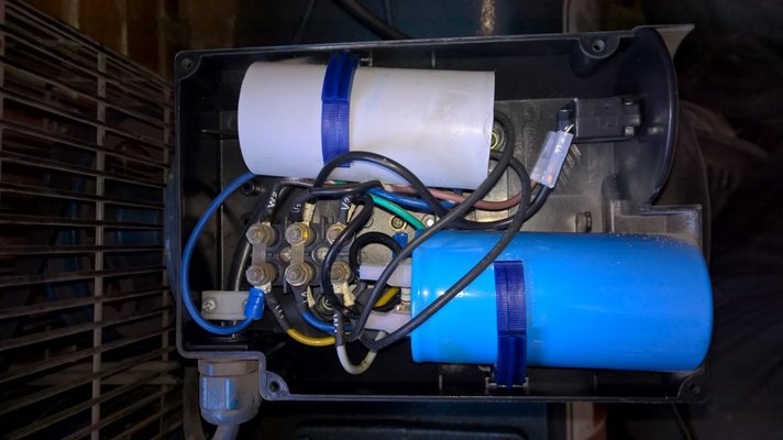
Clarke single phase motor wiring diagram. This type of motor is designed to provide strong starting torque and strong running for applications such as large water pumps. However i am at a loss at how to wire it. Other fans as shown brown black blue m 1 greeny ellow brown cap black ce31 only single phase ac motor with capacitor blue or grey a n sildes these diagrams mainly apply to external rotor motorsbut some standard. This video will show you how to connect a single phase motor with two capacitors. 1ø wiring diagram diagram er4 1ø wiring diagrams m 1 lne 3 active wires plus auto reset thermal contacts codes. I have been trying to google it for 3 days but am getting conflicting answers.
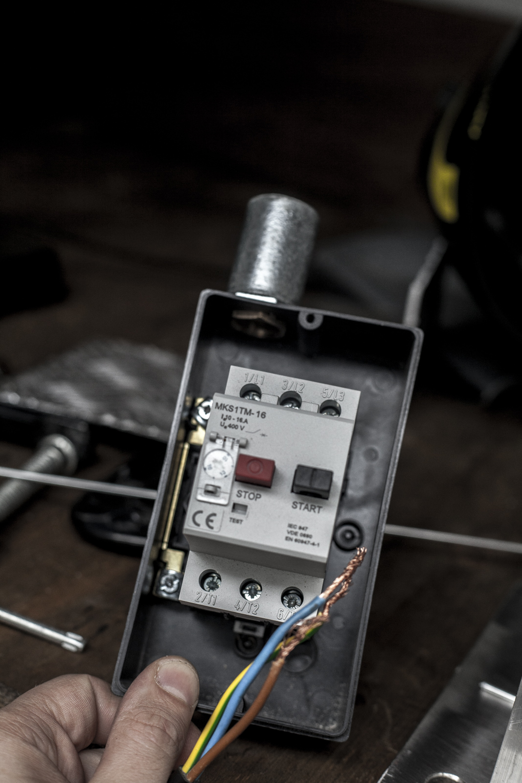
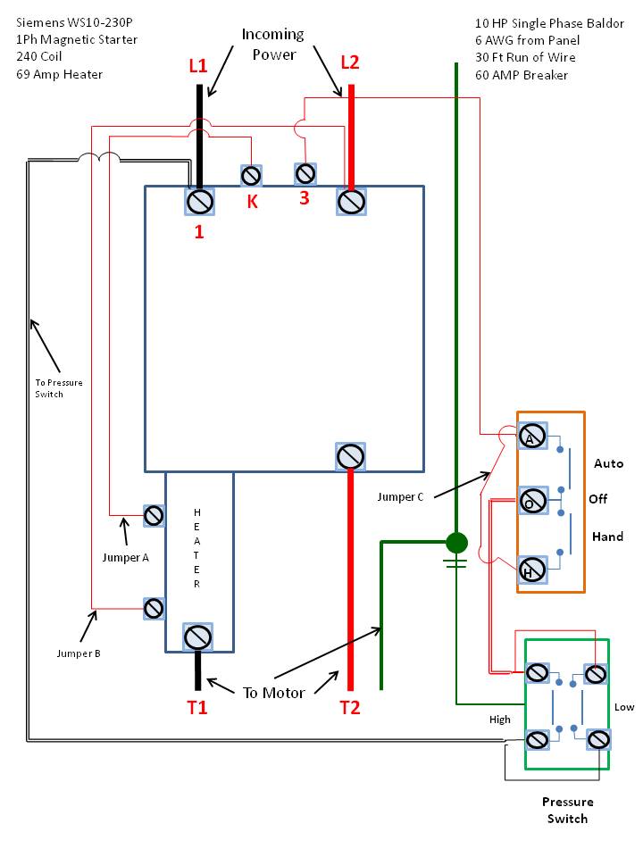
Also read about the speed torque characteristics of these motors along with its different types. In this video jamie shows you how to read a wiring diagram and the basics of hooking up an electric air compressor motor. Frequent stopstarts andor changing of the direction of rotation will damage the motors capacitors and winding. Click here to view a capacitor start motor circuit diagram for starting a single phase motor. The above diagram is a complete method of single phase motor wiring with circuit breaker and contactor. I have recently fitted a new pump pressure switch and a 22kw3hp single phase 240v 2 pole electric to my compressor.
Wiring diagram single phase motors 1empc permanent capacitor motors 1empcc capacitor start capacitor run motors. Wondering how a capacitor can be used to start a single phase motor. In many cases the single phase motors on board aplease check my motor wiring diagram mig welding forum. Just as in the three phase motor diagram the motor shows the power supply lines as being identified with the t. Residential power is usually in the form of 110 to 120 volts or 220 to 240 volts. A motor with a start and run capacitor and a start and run coil.
Wiring a motor for 230 volts is the same as wiring for 220 or 240 volts. It is a start capacitor and start run. Capacitor start capacitor run induction motors are single phase induction motors that have a capacitor in the start winding and in the run winding as shown in figure 12 and 13 wiring diagram. For most shore facility applications this is the case. Learn how a capacitor start induction run motor is capable of producing twice as much torque of a split phase motor. In the above one phase motor wiring i first connect a 2 pole circuit breaker and after that i connect the supply to motor starter and then i do cont actor coil wiring with normally close push button switch and normally open push button switch and in last i do connection between capacitor.
These tips can be used on most electric motor brands such as weg baldor.
