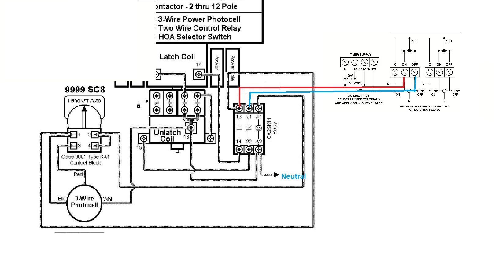
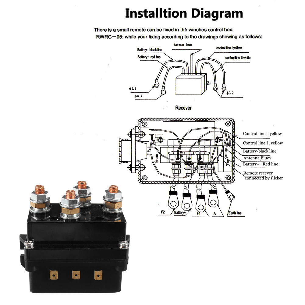
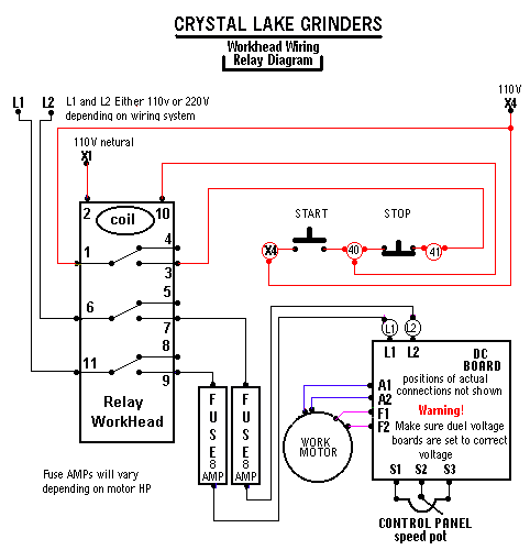
A wiring diagram is a simplified traditional photographic depiction of an electrical circuit. Each component should be placed and linked to other parts in particular manner.

1ccf3f Reverse Polarity Contactor Wiring Diagram Wiring Library
Contactor relay wiring diagram. Variety of 2 pole contactor wiring diagram. Contactor wiring and i hope after this post you will be able to wire a 3 phase motor i also published a post about 3 phase motor wiring with magnetic contactor and thermal overload relay but today post and contactor wiring diagram is too simple and easy to learn. It reveals the components of the circuit as streamlined forms and the power and signal links in between the tools. Easy and simple wiring diagram to make you learn easily watch the video and subscribe my youtube channel air. Its is important to. On delay timer circuit diagram wiring diagram contactor with push button circuit diagram of delay timer on off power off delay timer circuit diagram 2 way lighting circuit triggering transformer push button fan switch light activated switch circuit diagram wd081 text.
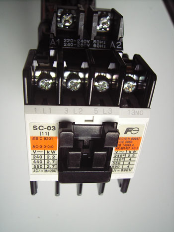
Wiring diagram for telemecanique lc1 contactor replacements by us breaker lr aux nc1d aux nc1d aux m control supply voltage is the same as the main circuit voltage 3 phase control supply voltage is not the same as the main circuit voltage 3 phase connect to other supply control supply voltage is the same. 2 days ago i wired 380 to 440 volts contactor for a 3 phase motor and save these images of contactor in pc. 240 volts ac and 480 volts ac are commonly used for these large pieces of. How to wire a contactor. Dol starter control and power wiring by using a fuse contactor overload relay motor. These lines far exceed the 120 volts ac standard in most homes.
Many large pieces of equipment are powered directly from high voltage lines.


