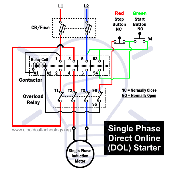
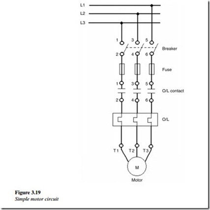
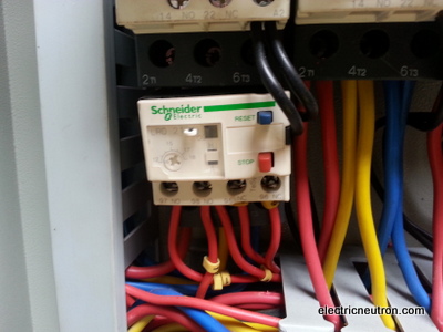
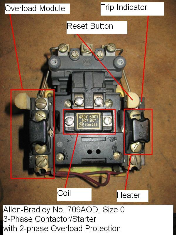
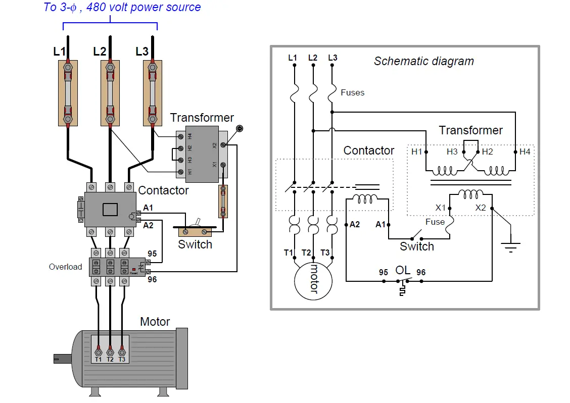
The overload contacts are connected in series and located between the contactor and the motor itself to prevent the motor from restarting once the overload trips. The above diagram is a complete method of single phase motor wiring with circuit breaker and contactor.

Allen Bradley Contactor Wiring Diagram Wiring Diagrams
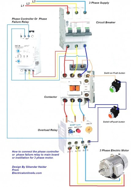
Contactor with overload wiring diagram. Then you connect the 2 motor leads to t1 and t3. The contactor will have space for the red power wires coming in from the photocell circuit breaker and lights. How to wire a contactor and overload. Dol motor starter with 230v contactor coil. How do i do a wiring to a single phase contactor via photocell to the outside lights. How to wire a contactor and motor protection switch.
Use transformer if you need to. The black power wires will need to be tied together. The below wiring diagram shows how we would assemble a complete motor starter with a startstop button for a single phase motor utilizing a 3 pole contactor. A wiring diagram is a streamlined traditional pictorial representation of an electrical circuit. A contactor is a large relay usually used to switch current to an electric motor or another high power load. In the above one phase motor wiring i first connect a 2 pole circuit breaker and after that i connect the supply to motor starter and then i do cont actor coil wiring with normally close push button switch and normally open push button switch and in last i do connection between capacitor.
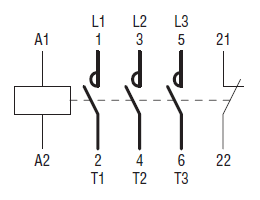
Variety of siemens overload relay wiring diagram. Contactor wiring diagram you will want a comprehensive professional and easy to know wiring diagram. The lights connect to the output ports on the contactor. These diagrams do not relate to such systems unless the 2 right hand pins are first removed. Its is important to. See our full product selection.
Large electric motors can be protected from overcurrent damage through the use of. Contactor wiring and i hope after this post you will be able to wire a 3 phase motor i also published a post about 3 phase motor wiring with magnetic contactor and thermal overload relay but today post and contactor wiring diagram is too simple and easy to learn. The tesys k range contactors lc1k and tesys lr overloads lr2k have additional pins on their overloads to make direct connection to terminals 14 on contactor to 95 on overload and a2 on contactor to 96 on overload. 2 days ago i wired 380 to 440 volts contactor for a 3 phase motor and save these images of contactor in pc. Using this method the current is balanced between the 3 poles on the overload. It shows the components of the circuit as simplified forms and the power and also signal links between the gadgets.
You must watch this video. With this kind of an illustrative guidebook you will be capable of troubleshoot prevent and complete your projects without difficulty. In a wiring diagram the symbol for overload contacts may look like two opposed question marks or an s.


