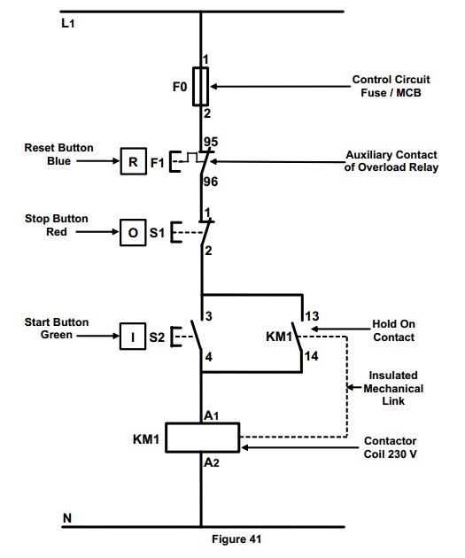
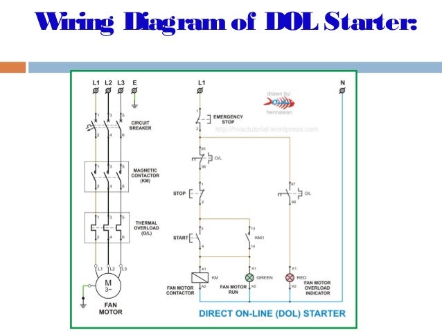
Dol starter control diagram three phase. Easy to understand and troubleshoot.
Clear Electronic Project Box Dol Starter Control Circuit
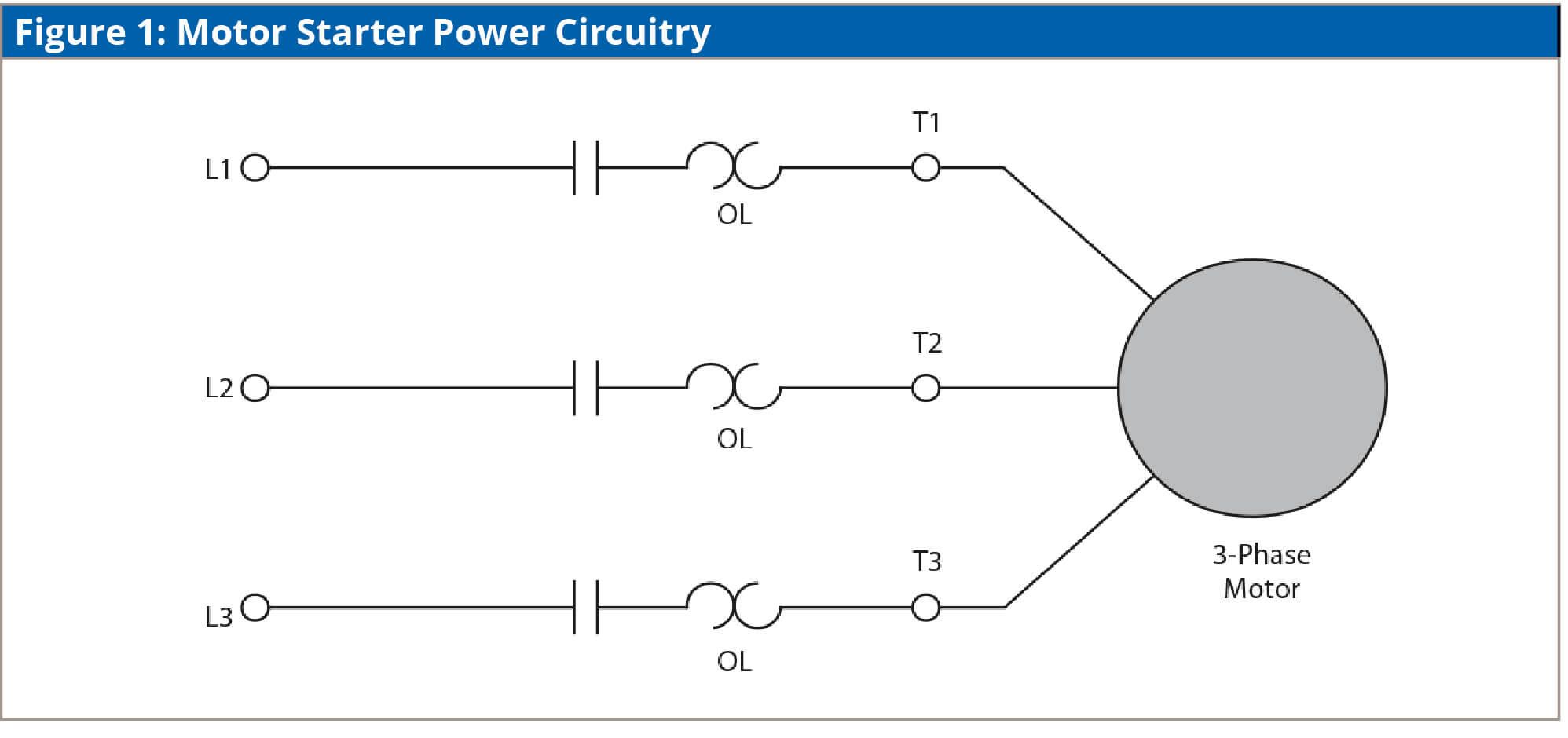
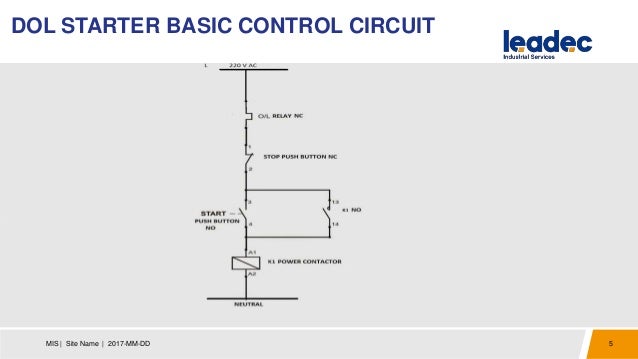
Control circuit diagram of dol starter. Simple to establish operate and maintain. A dol starter is a direct on line motor starter. All controlling of starter are controlled by this circuit. Dol starter control circuit diagram consist components like main power contactor start button stop push button and overload relay is connected in series this circuit is called control circuit of dol motor starter. Sometimes known as an across the line starter this type of motor controller is used as a simple starter for larger electric motors providing. The control circuit is connected to any two phases and energized from them only.
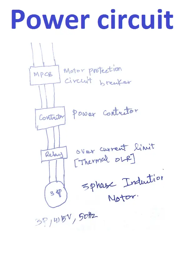
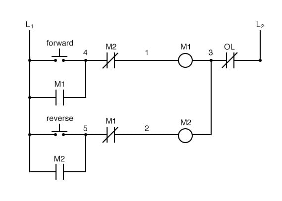
The wiring of direct on line control circuit starter is following. Most economical and cheapest starter. The connection of contactor can be done among relay coil supply voltage as well as thermal overload. The circuit breaker is used for protection against short circuits while the overload relay protects the motor from overloading. Note that the single phase dol starter wiring diagram is also like this. You can also connect timer limit switches float switch reverse forward remote.
Only one set of cable is required from starter to motor. The contactor is used for starting and stopping the motor where the green and red buttons are connected. In this post we are going to know the details of each part of dol starter diagramall parts of the dol starter power circuit diagram and control circuit diagram are explaineddirect online starter or dol starter is very useful and commonly used ac starterdol starters are mainly used with up to 5 hp motors. Single phase motor dol starter connection diagram. Advantages of dol starter. When we press the start button the current flows through contactor coil magnetizing coil and control circuit also.
It provides 100 torque at the time of starting. 3 phase motor contactor wiring diagram. And one wiring is called controlling wiring. The working principle of a dol starter begins with the connection to the 3 phase main with the motor. One wiring called main wiring which is used for motor. Motor is connected in delta at motor terminals.
In the below dol starter wiring diagram i shown a molded case circuit breaker a magnetic contactor normally open push button normally close push button switch thermal overload. The l1 contactor is connected from normally open no to r phase using mccb. The dol starter is made of a circuit breaker or mccb or fuse an overload relay and contactor or coil. How dol starter control diagram works when we press the start button to start the motor the relay gets the phase and circuit completed thus coil energizes and contactors produce magnetic field the main contactor closes and motor gets the supply and the motor startswhen we press the stop button the circuit will interrupt and the motor stop. In three phase dol starter wiring the two types of wiring done. And if you want to learn about the dol starter wiring for single phase then read the below post.
Dol starter working principle.


