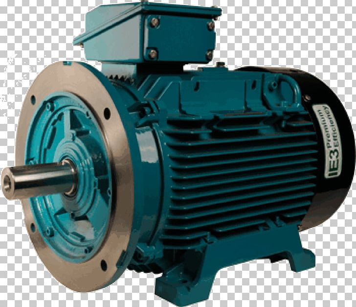
Dependent on the application we are able to offer different types of single phase motors. How do i wire my motor.

6 Lead Motor Wiring Diagram Dc Wiring Diagram Source
Crompton greaves single phase motor wiring diagram. Diagram dd6 diagram dd7 m 1 ln e diagram dd8 ln e l1 l2 l3 sc z1 u2 z2 u1 cap. Wiring a crompton parkinson 14 12 wiring. Two speed motors for all other single phase wiring diagrams refer to the manufacturers data on the motor. Also read about the speed torque characteristics of these motors along with its different types. Here are a few notes about wiring up my small lathe motor. Values of performance characteristics for three phase induction motors.
Im trying to wire up a motor for my myford ml7. Thermal contacts tb white m 1 z2 yellow z1 blue u2 black u1 red bridge l1 and l2 if speed controller sc is not required m 1 ln e white brown. From standard starters components and accessories to fully customised industrial and bms control panel solutions. Single phase motors are used primarily in small workshops and farms with a domestic supply. Some industrial equipment are specifically for use with a single phase electricity supply such as fans blowers centrifugal pumps and high pressure washers. They are specific to the particular motor referred to in the title and shown in the photos 250w 29a 50hz 220240v ac.
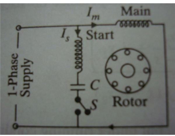
Brooks crompton parkinson motors had a small sheet metal cover on the motor end bell that revealed the terminals when the two screws were removed. Wondering how a capacitor can be used to start a single phase motor. Connection diagram for tefc two speed motors connection diagram for tefc dual voltage motors 65 terminal box arrangement frame ad 6371 3 lead 66 frame ad 6371 6 lead 67. Here is a wiring diagram of a capacitor start single phase motor. Forward wiring starter winding. Click here to view a capacitor start motor circuit diagram for starting a single phase motor.
Brook crompton wiring diagram brook crompton parkinson motors wiring diagrams brook crompton motor wiring diagram brook crompton hr0910 wiring diagram brook crompton single phase wiring diagrams ikwalrep mannheimde. Single speed three phase induction motors for driving lifts. At crompton controls we design manufacture and distribute worldwide from our centrally based operation in the uk. Motor winding crompton greaves 75hp duration. Note that in this and most diagrams available on the internet the centrifugal switch is shown in the open position leading people to think thats how it is supposed to be wired but its kind of a mistake in the depictions. The notes are simply to show my own set up.
Specialists in electric motor control equipment. Brook crompton single phase motor rotation change duration. On the inside of the cover was a paper sticker with the motor wiring diagram listing the terminals that needed power and which wires to change to reverse motor rotation. Learn how a capacitor start induction run motor is capable of producing twice as much torque of a split phase motor. Wiring up a brooke crompton single phase lathe motor myford lathe.


